Orthodontic bracket

a bracket and orthodontic technology, applied in dentistry, medical science, dental tools, etc., can solve the problems of increasing the area where food particles are located, the small size of the ligature or ligating module requires substantial time for the installation of the archwire, and the ligature or ligating module also presents limitations in terms of the force exerted on the brack

Active Publication Date: 2009-11-24
ORTHODONTIC RES & DEV
View PDF74 Cites 101 Cited by
  • Summary
  • Abstract
  • Description
  • Claims
  • Application Information

AI Technical Summary

Problems solved by technology

The small size of the ligatures or ligating modules requires substantial time for installation of the archwire.
Because the orthodontist will typically make numerous adjustments to the archwire throughout orthodontic treatment, the orthodontist will likely remove and replace the ligatures or ligating modules numerous times. Hygiene is another problem since the use of ligatures or ligating modules increases the areas where food particles may be trapped.
Ligatures or ligating modules also present other limitations in terms of the forces exerted upon the brackets.
For example, the labial or outward force that may be applied to a tooth having a bracket bonded to its labial surface is limited to the strength of the ligature or ligating module in the labial direction.
However, most of those have complex designs, incorporating features requiring prohibitively expensive machining operations or comprising multiple separate parts, which in turn increases the number of failure modes for such brackets.
Other designs have been rejected in the marketplace due to poor quality or poor design, a lack of available features, difficulty of use, or other factors.

Method used


Image

  • Orthodontic bracket
  • Orthodontic bracket
  • Orthodontic bracket

Examples


Embodiment Construction

[0026]In the following detailed description, numerous specific details are set forth in order to provide a thorough understanding of the present invention. However, those skilled in the art will understand that the present invention may be practiced without these specific details, that the present invention is not limited to the depicted embodiments, and that the present invention may be practiced in a variety of alternate embodiments. In other instances, well known methods, procedures, components, and systems have not been described in detail.

[0027]Various operations will be described as multiple discrete steps performed in turn in a manner that is helpful for understanding the present invention. However, the order of description should not be construed as to imply that these operations are necessarily performed in the order they are presented, nor even order dependent.

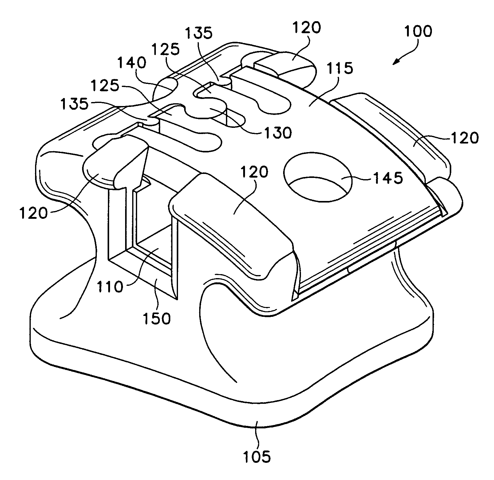
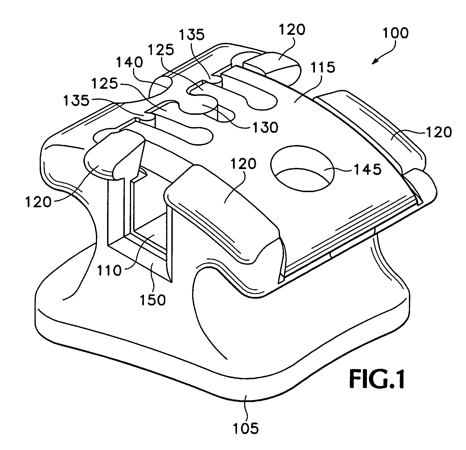
[0028]Turning now to the several drawings, FIG. 1 illustrates an isometric view of a self-ligating orthodontic bra...


PUM


Abstract

The present invention provides an improved self-ligating orthodontic bracket. According to one embodiment, the improved orthodontic bracket includes a mounting base for attachment to a tooth surface, an archwire slot formed upon the base and sized for receiving an orthodontic archwire, a channel formed upon the base and transversely oriented to the archwire slot, and a ligating slide member slideably retained within the channel and closeable over the archwire slot for retaining the orthodontic archwire therein, and wherein the ligating slide member includes at least one coplanar resilient retention mechanism for exerting retention forces coplanar with the ligating slide member for holding the ligating slide member in a closed position. In one embodiment, the improved orthodontic bracket comprises a bracket with a ligating slide member slideably retained within a dovetail shaped channel.

Description

CROSS-REFERENCE TO RELATED APPLICATIONS[0001]This application is a continuation-in-part of U.S. patent application Ser. No. 10 / 535,614, filed on May 19, 2005, which is a National Stage of International application Ser. No. PCT / ES2003 / 000594, filed Nov. 25, 2003, which claims the benefit of Spanish Patent Application No. 200202713, filed Nov. 26, 2002. The specifications of the above applications are incorporated herein by reference.BACKGROUND OF THE INVENTION[0002]This disclosure relates to improved self-locking or ligatureless orthodontic brackets.[0003]Orthodontic treatment generally comprises dental work to correct irregularities of the teeth or of the relation of the teeth to surrounding anatomy. The irregularities may involve malocclusions with varying degrees of severity. Class 1 malocclusions, for example, may involve spacing irregularities such as excessive crowding or diastema (a gap between two adjacent teeth). Class 2 malocclusions may involve overbite conditions where th...

Claims


Application Information

Patent Timeline
Patent Type & Authority Patents(United States)
IPC IPC(8): A61C3/00A61C5/08A61C7/28
CPCA61C7/287
Inventor BATHEN, JUERGENCARRIERE LLUCH, LUIS
Owner ORTHODONTIC RES & DEV
Why Eureka
Try Eureka