Retractable USB stick
a usb stick and retractable technology, applied in the direction of live contact access prevention, record carriers used with machines, instruments, etc., can solve the problems of imposing performance degradation, difficult configuration, and susceptible to ip spoofing
- Summary
- Abstract
- Description
- Claims
- Application Information
AI Technical Summary
Benefits of technology
Problems solved by technology
Method used
Image
Examples
embodiment 1
[0104]This embodiment is based on the above-referenced above-reference dispensing holder (U.S. Pat. No. 3,941,489) for cosmetic stick product and the like.
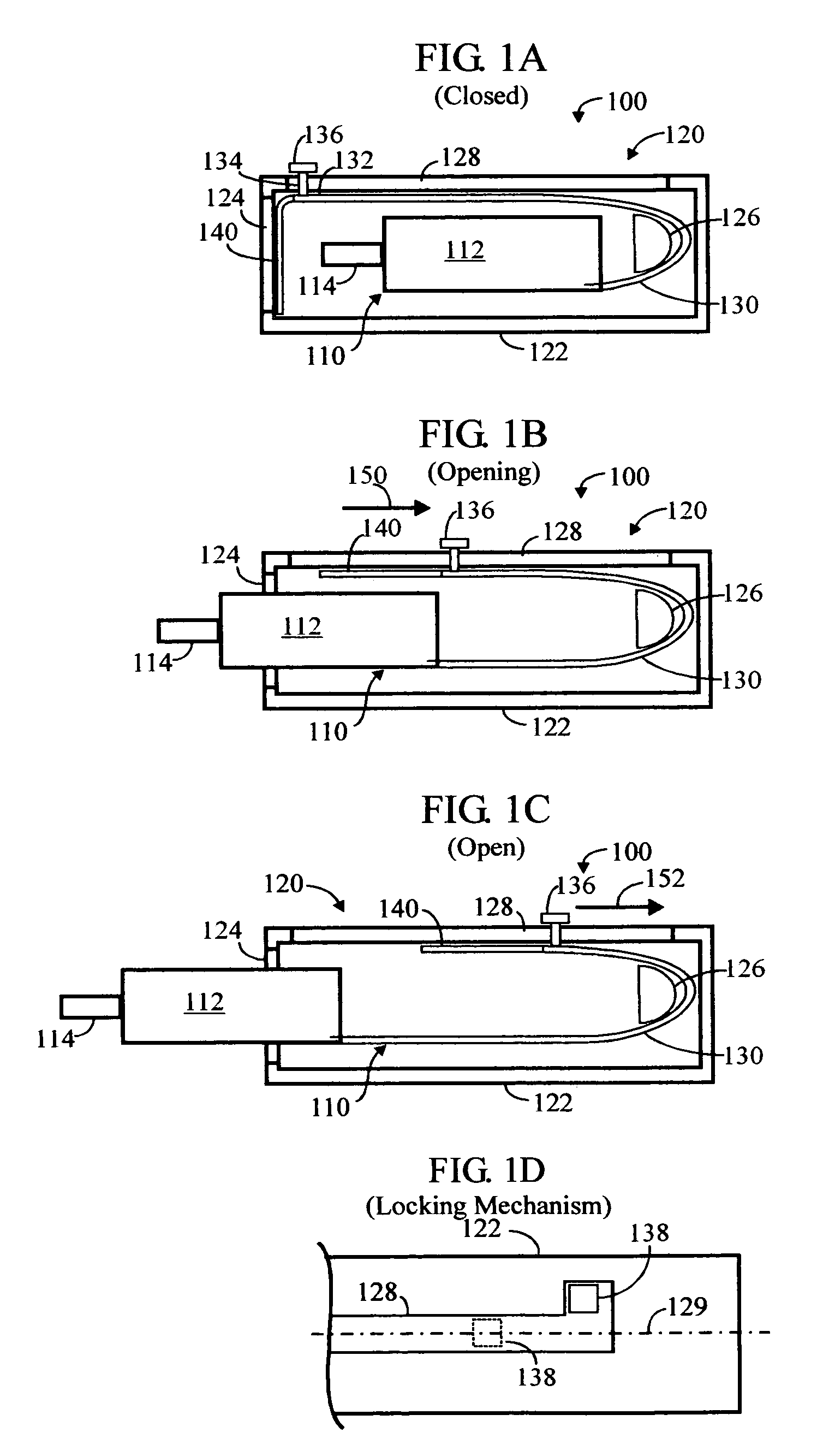
[0105]FIGS. 1A, 1B, 1C and ID illustrate an embodiment 100 of a USB stick 110 in a dispensing holder 120 in three positions—Closed, Opening, and Open, respectively.
[0106]The USB stick 110 comprises an elongate main body 112 and a USB connector 114 at its front end (left, as shown) of the main body 112.
[0107]The dispensing holder 120 comprises an elongate housing 122, with an opening 124 at its front end (left, as shown) of the housing 122.
[0108]An elongate strap 130 extends from the back (right, as viewed) end of the main body 112, towards the back (right, as viewed) end of the housing 122, wraps around a fixed boss 126 disposed near the opposite end of the housing, then back towards the front end housing, passing alongside of the USB stick 110, to the front end of the housing 122.
[0109]In the closed position (FIG. 1A), the far en...
embodiment 2
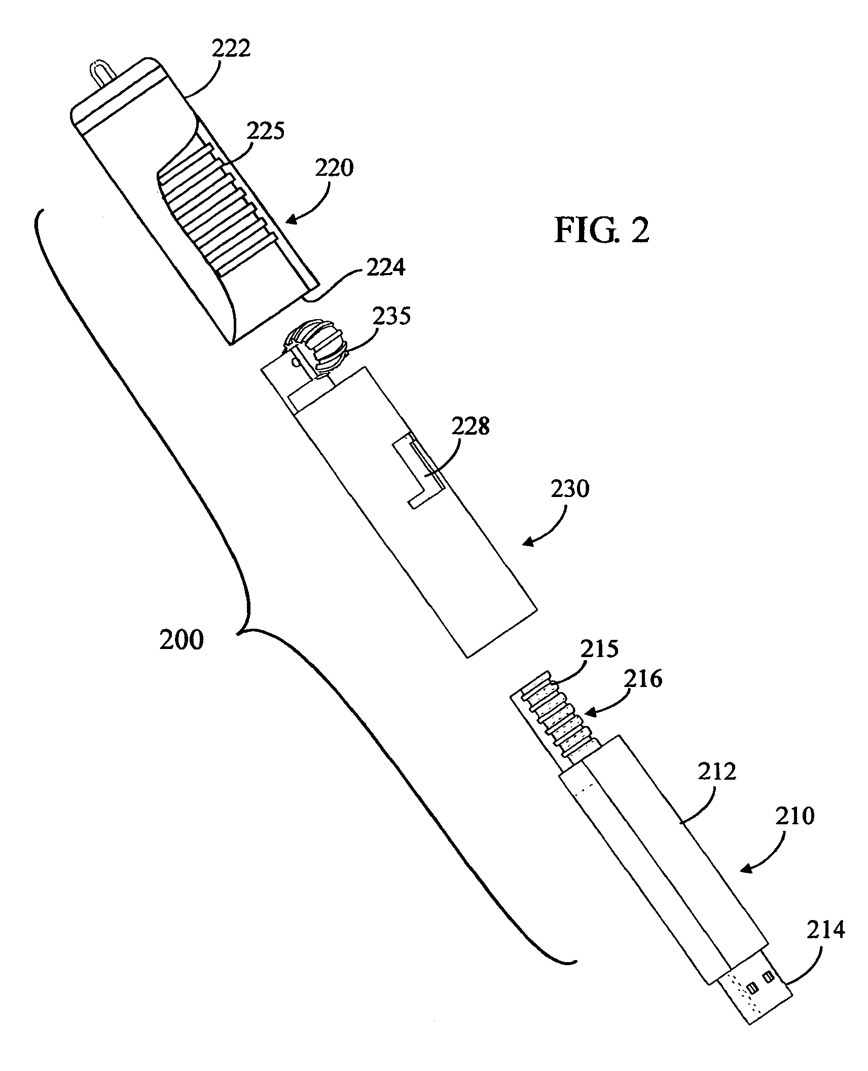
[0128]FIGS. 2, 2A, 2B and 2C illustrate another embodiment 200 of the invention, which incorporates a “reverse motion” feature as well as completely enclosing the USB stick in the “closed” position, using a different mechanism than was described in the previous embodiment. FIG. 2 is an exploded perspective view. FIGS. 2A, 2B and 2C are side cross-sectional views corresponding to FIGS. 1A, 1B and 1C in that they show the apparatus 200 in “closed”, “opening” and “open” positions, respectively.
[0129]The apparatus 200 comprises three main components:[0130]an inner USB stick 210 (compare USB stick 110);[0131]an outer holder 220 (compare holder 120); and[0132]an intermediate sleeve 230 (compare strap 130).
[0133]Referring to FIG. 2, the inner USB stick 210 comprises an elongate main body 212 (compare 112) and a USB connector 214 (compare 114) at its front end (bottom right, as shown) of the main body 212. A toothed, elongate, linear track 216 extends from the back (upper left, as viewed) e...
embodiment 3
[0148]FIGS. 3, 3A, 3B and 3C illustrate another embodiment 300 of the invention. This embodiment does not incorporate a “reverse motion” feature, and only partially encloses the USB stick in the “closed” position. However, it is “retractable”, as are the previously-described embodiments. FIG. 3 is a perspective view. FIGS. 3A, 3B and 3C are side cross-sectional views corresponding to FIGS. 2A, 2B and 2C in that they show the apparatus 300 in “closed”, “opening” and “open” positions, respectively.
[0149]The apparatus 300 comprises three main components:[0150]an inner USB stick 310 (compare USB sticks 110, 210);[0151]an outer holder 320 (compare holder 120, 220); and[0152]an intermediate support 330 (compare strap 130, 330).
[0153]Referring to FIG. 3, the USB stick 310 comprises an elongate main body 312 (compare 112, 212) and a USB connector 314 (compare 114, 214) at its front end of the main body 312.
[0154]The outer holder 320 comprises an elongate housing 322 with an opening 324 at i...
PUM
 Abstract
Description
Claims
Application Information
 - R&D
- Intellectual Property
- Life Sciences
- Materials
- Tech Scout
- Unparalleled Data Quality
- Higher Quality Content
- 60% Fewer Hallucinations
Browse by: Latest US Patents, China's latest patents, Technical Efficacy Thesaurus, Application Domain, Technology Topic, Popular Technical Reports.
© 2025 PatSnap. All rights reserved.Legal|Privacy policy|Modern Slavery Act Transparency Statement|Sitemap|About US| Contact US: help@patsnap.com


