Display device and light adjusting method thereof

a technology of light adjusting and display device, which is applied in the direction of picture reproducers, identification means, instruments using projection devices, etc., can solve the problems of inability to efficiently adjust the light adjusting large correcting circuit, complicated light spectral variation of a white light source, etc., to promote image quality improvement and flexible and proper light control signal setting

Active Publication Date: 2009-12-29
SEIKO EPSON CORP
View PDF44 Cites 64 Cited by
  • Summary
  • Abstract
  • Description
  • Claims
  • Application Information

AI Technical Summary

Benefits of technology

[0007]It is an object of the invention to provide a display device and a light adjusting method thereof capable of effectively carrying out light adjustment by the output control of light sources and, preferably, of light adjustment depending on the color distribution of a displayed image.
[0032]By applying the different value for setting the light control signal for each image signal as described above, it is possible to set the light control signal more flexibly and properly, and to promote image quality improvement of the displayed image upon light adjustment.

Problems solved by technology

However, although a technique described in the Japanese Unexamined Patent Application Publication No. 11-296127 is employed, light emitting spectral variation of a white light source is complicated and a large sized correcting circuit is required.
Further, in cases in which there is deflection in color distribution of a displayed image, efficient light adjustment in a white light source cannot be carried out, and then effects by light adjustment cannot be sufficiently obtained.

Method used


Image

  • Display device and light adjusting method thereof
  • Display device and light adjusting method thereof
  • Display device and light adjusting method thereof

Examples


Embodiment Construction

[0043]Hereinafter, embodiments of the invention will be described with reference to the accompanying drawings.

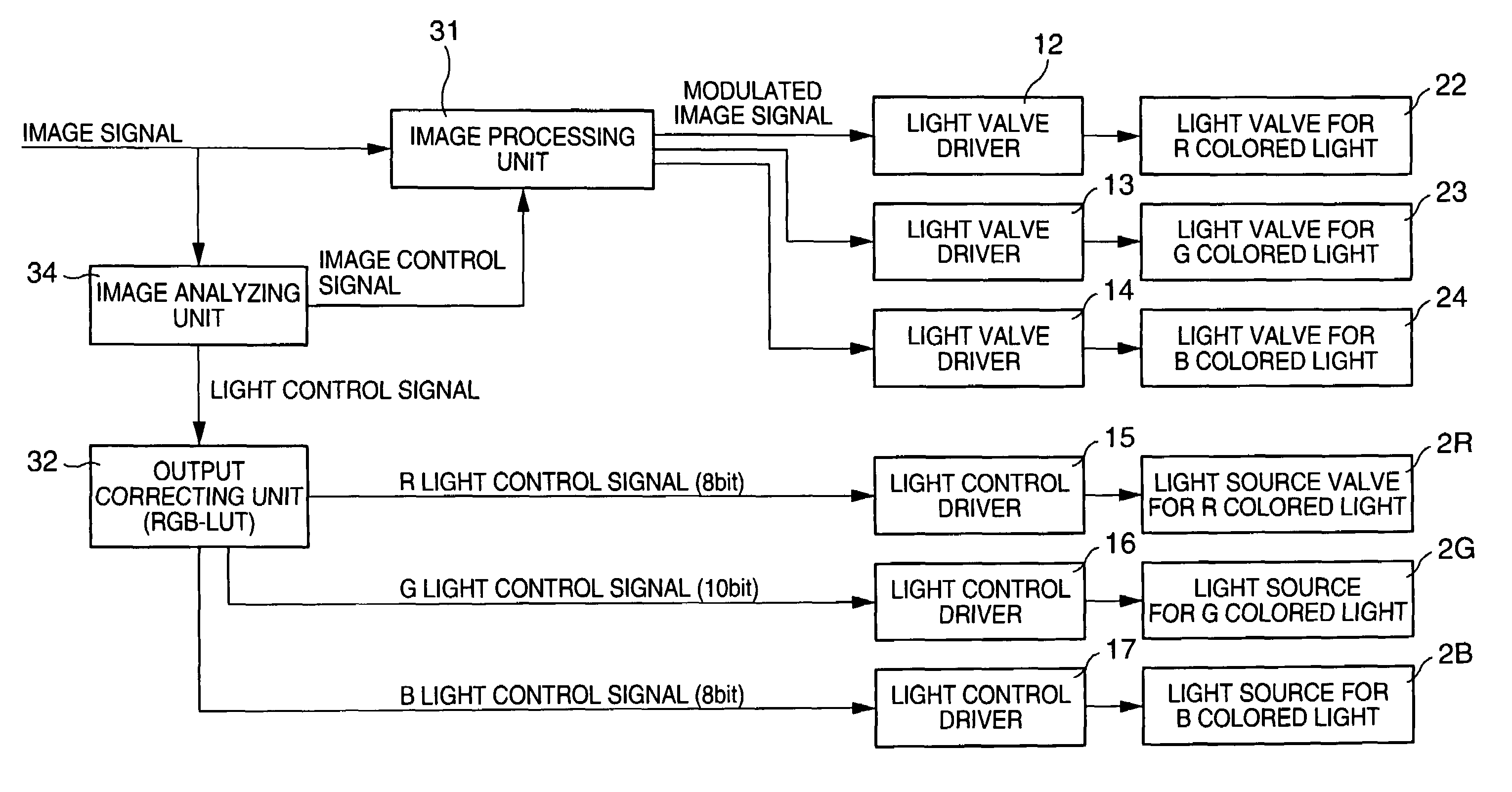
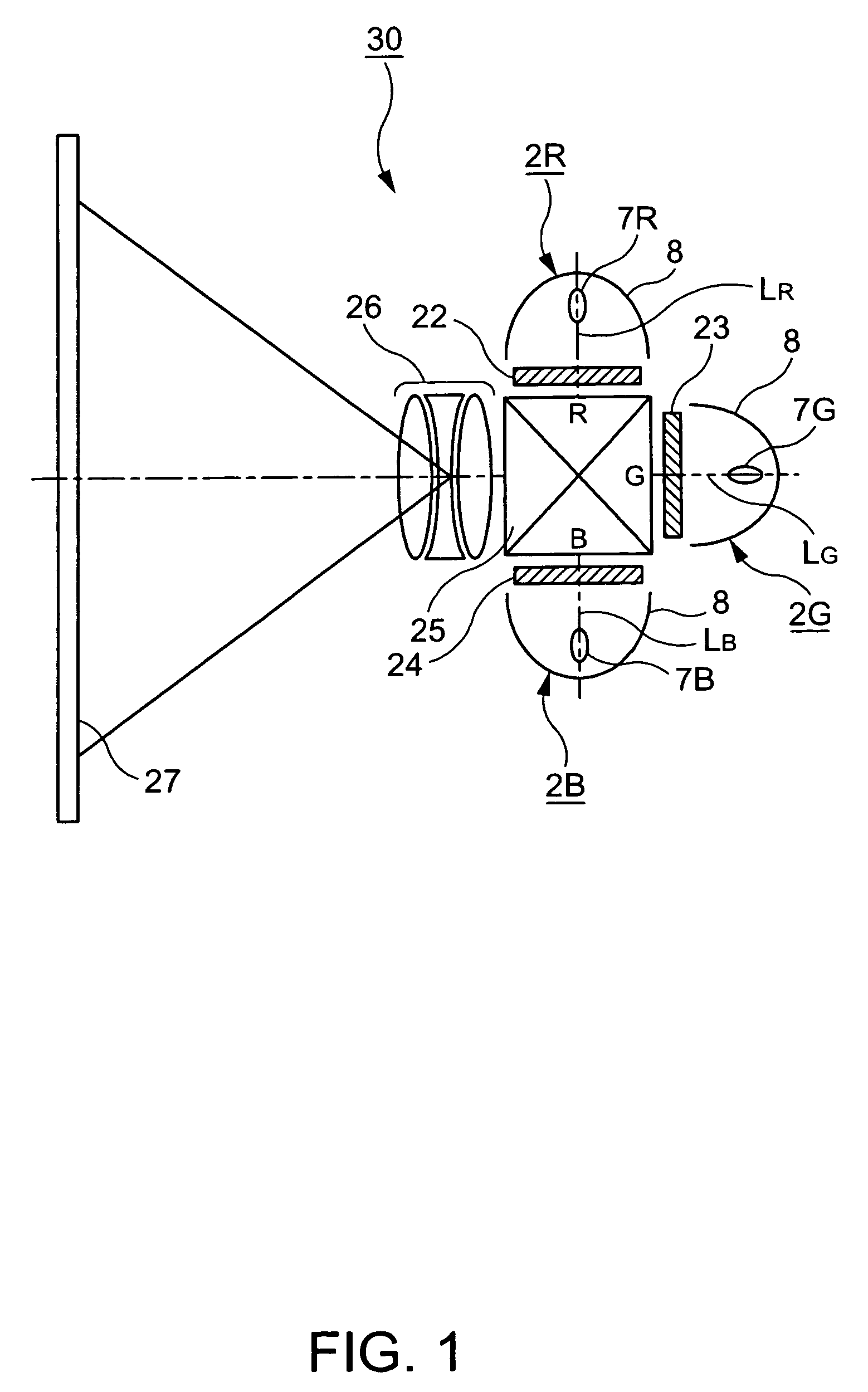
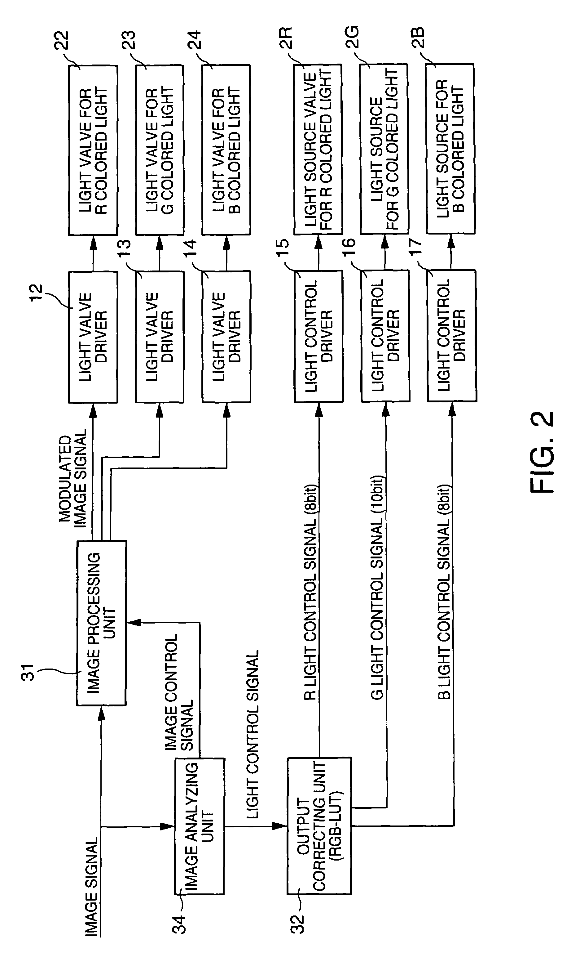
[0044]FIG. 1 is a schematic configuration diagram of a projection type display device, which is a first embodiment of a display device according to the invention. A projection type display device 30, shown in FIG. 1, comprises light sources 2R, 2G and 2B, each capable of emitting different colored light component, liquid crystal light valves (light modulating means) 22 to 24, a dichroic prism 25, and a projection system 26. A reference numeral 27 is a screen on which an image is projected and displayed.

[0045]The light source 2R is composed of a lamp 7R for emitting a red colored light component LR, and a reflector 8 for reflecting the light of the lamp 7R. The light source 2G is composed of a lamp 7G for emitting a green colored light component LG, and a reflector 8 for reflecting the light of the lamp 7G. The light source 2B is composed of a lamp 7B for emitting a blue colo...


PUM

PropertyMeasurementUnit
luminanceaaaaaaaaaa
luminance distributionaaaaaaaaaa
coloraaaaaaaaaa

Abstract

The invention provides a display device and a light adjusting method thereof capable of carrying out light adjustment effectively by the output control of a light source and, preferably, of effecting light adjustment according to color distribution of a displayed image. The display device of the invention that is capable of adjusting a displayed image by changing light flux can include a plurality of light sources having light emitting diodes, an image analyzing unit for outputting a light control signal for controlling the output of each of the light sources, based on an image signal of the displayed image, and a light control device for controlling the output of each of the light sources based on the light control signals.

Description

BACKGROUND OF THE INVENTION[0001]1. Field of Invention[0002]The present invention relates to a display device and a light adjusting method thereof.[0003]2. Description of Related Art[0004]A conventional projection type display device can have the following problems. Because of leaked light or stray light that occurs in several optical elements constituting an optical system, sufficient contrast is not obtained. That is, the displayable brightness range (dynamic range) is narrow, and image quality is inferior as compared to an existing image monitor using a cathode ray tube (hereinafter, referred to as CRT). Although quality improvement of an image is sought by various image signal processes, it is impossible to exhibit sufficient effects because of a fixed dynamic range.[0005]As a solution for the problems associated with such a projection type display device, namely, a method of expanding the dynamic range, it can be considered to change the flux of a light component incident to th...

Claims


Application Information

Patent Timeline
Patent Type & Authority Patents(United States)
IPC IPC(8): G03G17/04G02B27/18G02F1/13G02F1/133G03B21/00G03B21/14G09F9/00G09G3/18G09G3/20G09G3/34G09G3/36H04N9/31
CPCH04N9/315H04N9/3197H04N9/3182
Inventor YOSHIDA, SHOHEIIISAKA, HIDEHITO
Owner SEIKO EPSON CORP
Why Eureka
Try Eureka