Gate latch

a technology of latching mechanism and gate post, which is applied in the direction of fastening means, mechanical devices, carpet fasteners, etc., can solve the problem that the gate or gate post will usually fail before the latch breaks

Inactive Publication Date: 2010-01-19
BOWERS CLIFFORD ALLEN
View PDF13 Cites 3 Cited by
  • Summary
  • Abstract
  • Description
  • Claims
  • Application Information

AI Technical Summary

Benefits of technology

[0005]In all embodiments of this invention, the components of the latch device are made of a sturdy material, preferably stainless steel. Stainless steel makes the device strong and durable, typically withstanding tensile forces up to 35,000 psi with a ¾ inch configuration. A forged, hardened clevis and locking pin would withstand tensile forces up to 70,000 psi with a ¾ inch configuration. Because of the strength of this material, the gate or gate post will usually fail before the latch breaks. The locking pin of the present invention allows the gate latch to be easily and quickly opened or closed. One convenience of the latch disclosed in this invention is that it can be used on any gate currently in use as an after market product. The gate does not need any special assembly as the latch can be attached to the gate with a few simple tools.
[0008]An alternative embodiment of the single hinge gate latch and the double hinge gate latch employs a clevis on which there is affixed a locking ring to one of the legs. The use of this locking ring eliminates the need for the locking sleeve. Once the locking pin is inserted through the openings of the clevis to secure the gate in the closed position, the handle end of the locking pin is rotated into contact with the locking ring affixed to the clevis. A lock may then be inserted through the opening in the end of the locking pin and the opening in the locking ring.

Problems solved by technology

Because of the strength of this material, the gate or gate post will usually fail before the latch breaks.

Method used


Image

  • Gate latch
  • Gate latch
  • Gate latch

Examples


embodiment 36

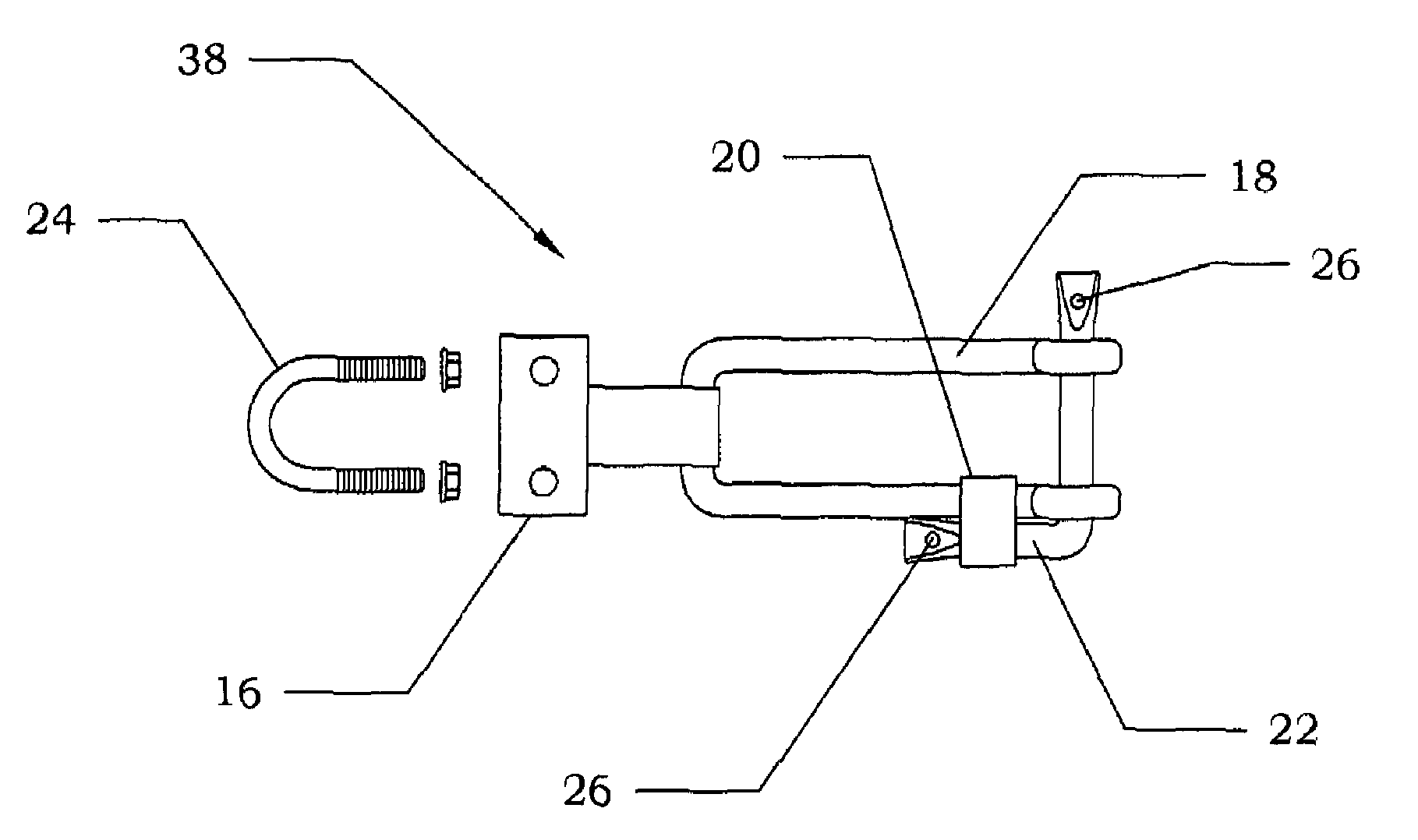
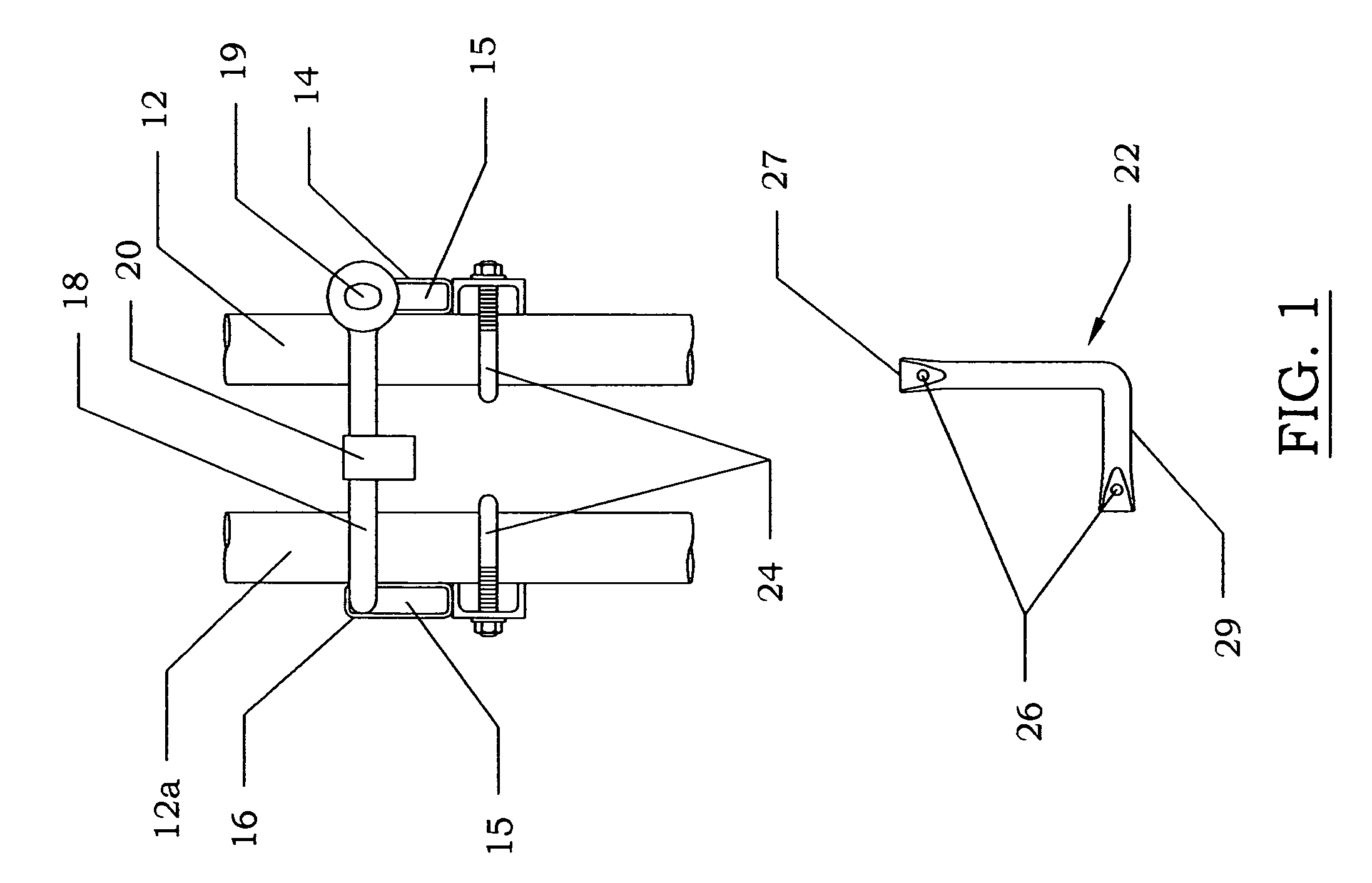
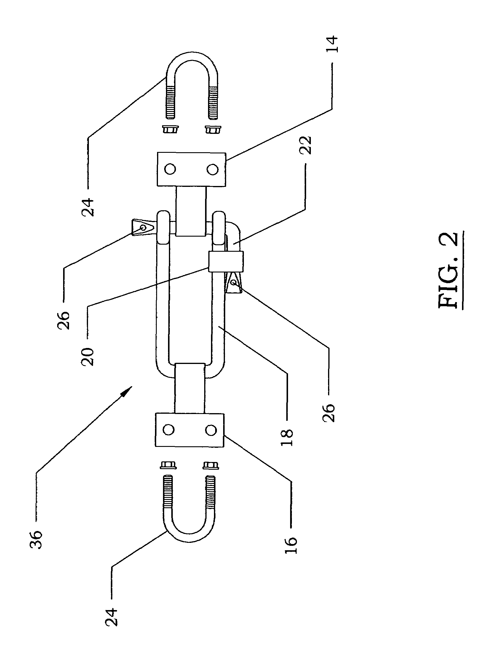
[0022]FIGS. 1 and 2 show the double gate latch embodiment 36. In this embodiment a locking hinge 14 is affixed to the outside of a gate frame 12, preferably with a U-bolt 24. An adjustable hinge 16 is affixed to the outside of a second gate frame 12a, preferably with a U-bolt 24. Both the locking hinge 14 and the adjustable hinge 16 contain openings 15 generally perpendicular to the plane of the gate. A U-shaped bar called a clevis 18 is inserted through the adjustable hinge 16. A top view of the clevis 18 is shown in FIG. 7. The clevis 18 can be made of any solid material, with the preferred material being stainless steel. The clevis 18 can be round or square in shape. In the preferred embodiment a square back clevis is used. The square back clevis 18 adds strength and durability to the invention for several reasons. Firstly, if force is applied to the clevis 18, the square back allows the force to be distributed along the entire width of the adjustable hinge 16, as opposed to only...

second embodiment

[0030]This second embodiment can be used with many different kinds of fences. Two examples include a chain link fence or a tubular steel gate. Different kinds of materials are used to construct different kinds of fences. Therefore, the mounting mechanism of the adjustable hinge 16 may change depending on what kind of material is used to construct the terminal post 10. For example, if the adjustable hinge 16 is attached to a wooden post, it may be attached with a nail or a bolt. However, if the adjustable hinge 16 is attaching to a steel post, it may be welded or secured with U-bolts.

[0031]The second embodiment does not have a locking hinge for the locking pin 22 to slide through; therefore, the locking pin 22 can be positioned through the gate frame 12 and under a sturdy structural member of the gate frame 12, such as a tubular bar. This takes weight off of the movable hinges of the gate by allowing the weight of the gate to be supported by the sturdy latch assembly. This may length...

fourth embodiment

[0033]FIG. 5 shows the invention called the roller gate latch 34. This latch system is for use with gates that slide shut, usually on rollers or any comparable mechanism. These gates operate in the same plane as the rest of the fence rather than having hinges that allow the gate to open at an angle to the fence line. The roller gate latch 34 comprises a gate receiver 28 that catches and guides the gate 12b into a latch gate cavity 31 as the gate 12b slides shut. The receiver 28 is comprised of an inside guide 28a with a flat end and a flared end, and an outside guide 28b with a flat end and a flared end. Each guide is positioned opposite from each other to define the latch cavity 31. Once in the latch cavity 31, a locking pin 22 is inserted through the gate receiver 28 to keep the gate closed. A lock is then inserted through the locking pin 22 and through a locking ring 30 attached to the gate receiver 28. The roller gate latch assembly body can be attached to any secure object thro...


PUM


Abstract

A latching and locking mechanism for fence gates or doors. The mechanism comprises a locking pin for selectively securing the gate in the closed position. When the locking pin is removed from a portion of the mechanism, the gate can easily be opened or closed. When the locking pin is inserted through a portion of the mechanism, the gate is held in a closed position. The locking pin can be locked in the closed position with a lock.

Description

[0001]This application is a divisional of U.S. patent application Ser. No. 10 / 248,333 filed Jan. 9, 2003 which is hereby incorporated by reference.BACKGROUND OF THE INVENTION[0002]This invention relates to a latching and locking mechanism for fence gates or doors. Gate latches generally provide a convenient way for securing fence gates in a closed position while still allowing the gate to be opened with minimal effort. Examples of fenced areas that may require these types of gate latches include cattle yards, stock yards for goods, and warehouses. One method used for locking a gate in a closed position is to wrap a length of chain around the gate and a sturdy gate post. However, there are several problems with using a chain in this manner. First of all, the chain links are often not as sturdy as the gate, and they can break when force is applied. A second problem is that it is difficult to secure the chain tight enough so the gate does not blow in the wind. Chains can also easily ge...

Claims


Application Information

Patent Timeline
Patent Type & Authority Patents(United States)
IPC IPC(8): E05C19/08E04H17/00
CPCE05C19/08Y10S292/17Y10S292/29Y10T292/31Y10T292/314
Inventor BOWERS, CLIFFORD ALLEN
Owner BOWERS CLIFFORD ALLEN
Why Eureka
Try Eureka