Lever-type connector

a connector and lever technology, applied in the direction of coupling device connection, coupling parts engagement/disengagement, electrical apparatus, etc., can solve the problems of cumbersome fitting operation, damage to the lever b>100/b>, and the engagement pin b>31/b> of the mating connector housing b>30/b>, so as to facilitate the displacement outwardly from each other, facilitate the effect of positive and positive

Inactive Publication Date: 2010-03-16
YAZAKI CORP
View PDF3 Cites 2 Cited by
  • Summary
  • Abstract
  • Description
  • Claims
  • Application Information

AI Technical Summary

Benefits of technology

[0031]Furthermore, in this lever-type connector, the distal end portions of the arm plates 12 are kept provisionally-fixed to the mating connector housing 30, with the engagement pins 31 received in the inlets 15a of the respective cam grooves 15. Therefore, once the connector is provisionally assembled, the two connector housings 20 and 30 are prevented from being inadvertently disconnected from each other, and in this provisionally-assembled condition, merely by pivotally moving the lever 100, the two connector housings 20 and 30 are easily connected together by the cam action achieved by the sliding movement between each cam groove 15 and the engagement pin 31.
[0046]According to the fourth aspect of the invention, the anti-slip portions are formed respectively on the outer surfaces of the distal end portions of the engagement cancellation lever portions, and therefore the operation for canceling the provisional fixing of the arm plates relative to the mating second connector housing is easily and positively carried out.

Problems solved by technology

When the provisionally-assembled condition is thus canceled, the two connector housings must be again provisionally assembled together before effecting the connector fitting operation, and there is a problem that the fitting operation may be cumbersome.
However, when the arm plates 12 are elastically bent outwardly away from each other by the jig, it is feared that the engagement pins 31 of the mating connector housing 30 and the lever 100 may be damaged.

Method used


Image

  • Lever-type connector
  • Lever-type connector
  • Lever-type connector

Examples


Embodiment Construction

[0058]An exemplary embodiment of the present invention will now be described with reference to the drawings.

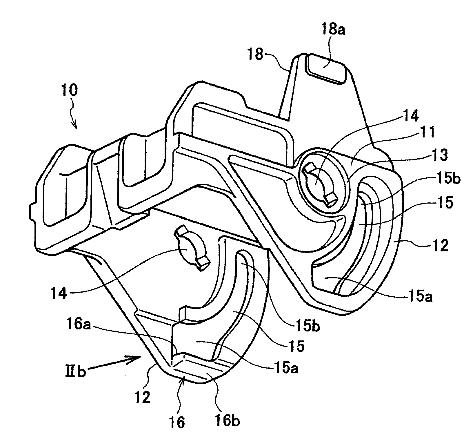
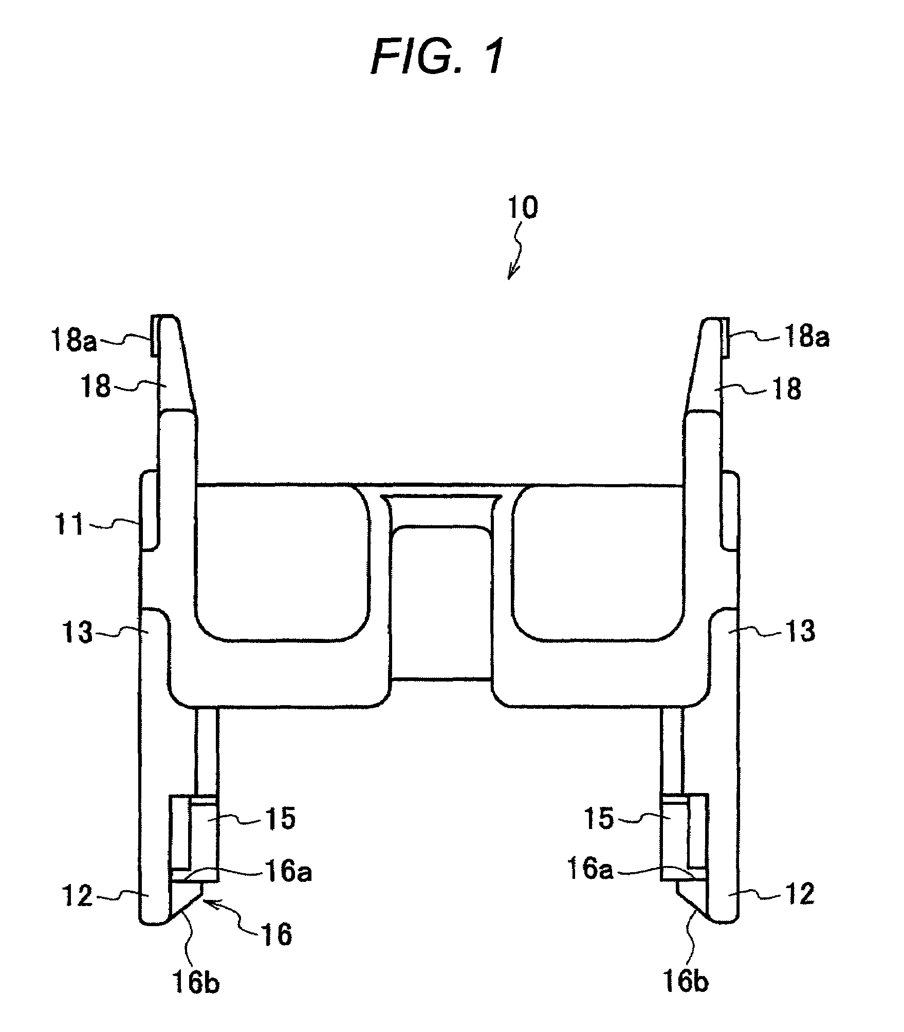
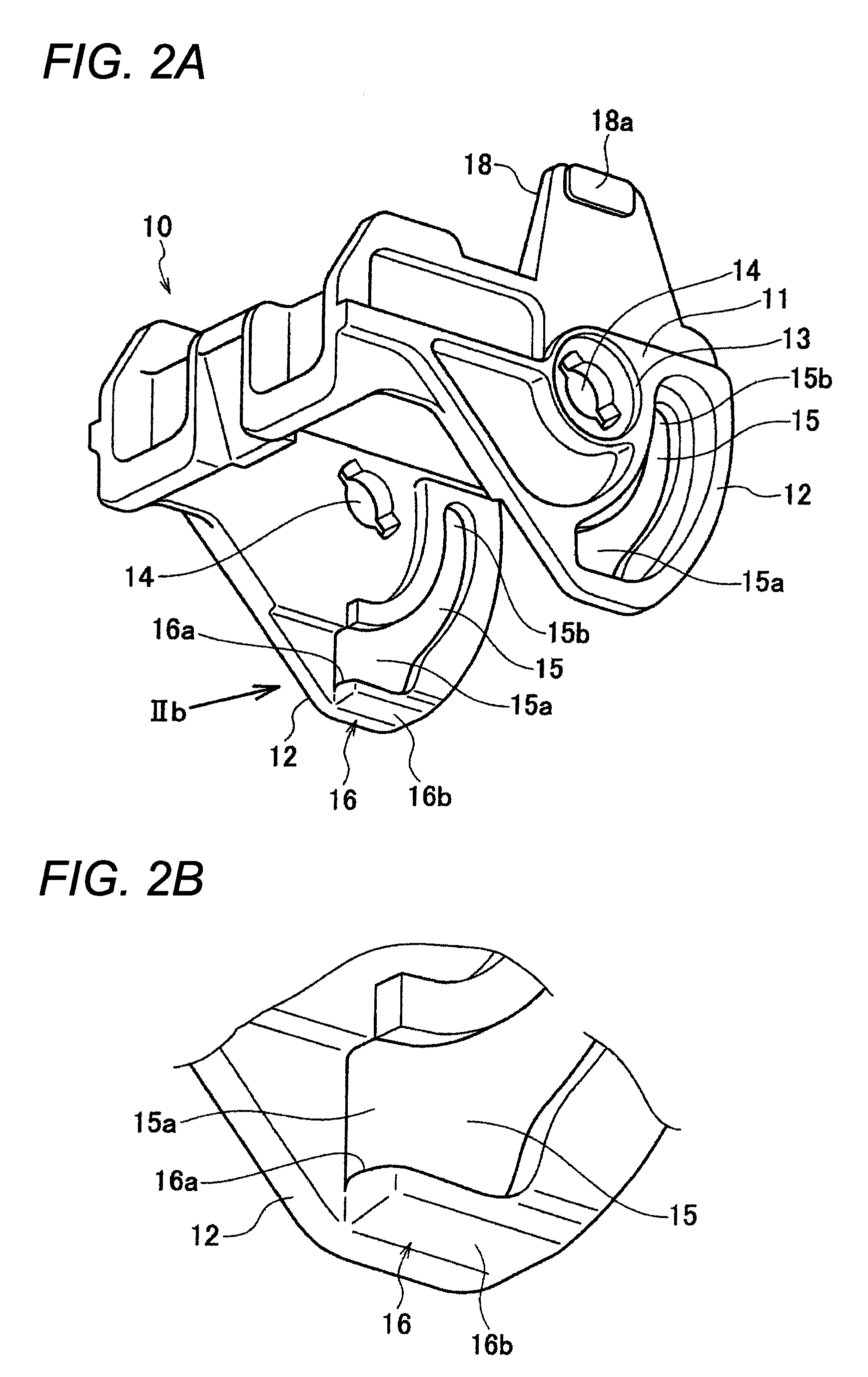
[0059]FIG. 1 is a front-elevational view of a lever used in one exemplary embodiment of a lever-type connector of the invention, FIG. 2A is a perspective view showing the construction of the lever, FIG. 2B is an enlarged view of a portion indicated by arrow IIb of FIG. 2A, and FIG. 3 is a front-elevational view showing the process of canceling the provisional fixing of distal end portions of arm plates relative to a mating connector housing.

[0060]As shown in FIG. 1, this lever-type connector comprises a pair of female and male (or first and second) connector housings 20 and 30 to be fitted together, and female metal terminals (not shown) are received respectively in terminal cavities of the first connector housing 20, and also male metal terminals (not shown) are received respectively in terminal cavities of the second connector housing 30.

[0061]The lever 10 of a generally U-s...


PUM


Abstract

A lever type connector comprises a first connector housing; a second connector housing including a projection; and a lever pivotally engaged with the first connector housing and including two arm plates and an interconnecting bar which connects the two arm plates. The each arm plate comprises a provisional-retaining projection projecting from the arm plate toward the other arm plate, which abuts to the projection and causes to deform the arm plate so that the arm plate recedes to the other arm plate when the projection is inserted into the cam groove; and a cancellation lever extending from an edge of the arm plate and positioned at a counter side of the inlet with respect to the pivotal support, which cause to deform the arm plate so that the arm plate recedes to the other arm plate when the cancellation lever is pressed to come close to the other cancellation lever.

Description

CROSS-REFERENCE TO RELATED APPLICATIONS[0001]This application claims priority from Japanese Patent Application No. 2008-156414 filed on Jun. 16, 2008, the entire subject matter of which is incorporated herein by reference.TECHNICAL FIELD[0002]This invention relates to a lever-type connector in which by pivotally moving a lever, male and female connector housings is brought into and out of fitting engagement with each other with a small force.BRIEF DESCRIPTION OF THE RELATED ART[0003]In the field of connectors such as a multi-pole connector in which a large fitting force is required, a lever-type connector which is provided with a lever for assisting the fitting force has been used.[0004]In such a lever-type connector, a lever having cam grooves is pivotally mounted on one of two connector housings to be fitted together, and engagement pins for engagement respectively in the cam grooves are formed in a projecting manner on the other connector housing. When the two connector housings ...

Claims


Application Information

Patent Timeline
Patent Type & Authority Patents(United States)
IPC IPC(8): H01R13/62
CPCH01R13/62938
Inventor SUGIYAMA, OSAMUKAZUNO, MASAHITOHARA, TERUFUMI
Owner YAZAKI CORP
Why Eureka
Try Eureka