Method of manufacturing image stabilizer

a technology of image stabilizer and manufacturing method, which is applied in the direction of television systems, instruments, printing, etc., can solve the problems of low work efficiency required upon manufacturing process, and achieve the effect of low number of parts required by position detectors, easy and positive control, and high accuracy

Inactive Publication Date: 2008-05-20
SONY CORP
View PDF5 Cites 14 Cited by
  • Summary
  • Abstract
  • Description
  • Claims
  • Application Information

AI Technical Summary

Benefits of technology

[0022]According to a method of manufacturing an image stabilizer of the present invention, since the Hall elements are used as the position detectors, the magnet of the driver can serve as the parts for giving necessary information to the Hall elements as well. Therefore, the number of parts required by the position detector can be decreased. Also, since the changes of the outputs from the Hall elements are large and the positional relationship between the magnet and the Hall elements can be adjusted to the position which changes substantially linearly, it is possible to easily and positively carry out controls for correcting a blurred image with high accuracy.
[0023]Also, according to a method of manufacturing an image stabilizer, since the magnetic flux density near the projected portions can be kept nearly uniform in the direction parallel to the edge of the magnet or the like, when the moving frame is moved to the first direction, the change of the magnetic flux density of the second Hall element can be decreased considerably. In a like manner, when the moving frame is moved to the second direction, the change of the magnetic flux density of the first Hall element can be decreased considerably. As a result, mutual interference between the first and second Hall elements can be decreased considerably and the position can be detected extremely accurately.
[0024]The first Hall element for detecting the correcting lens that moves in the first direction, the second Hall element for detecting the correcting lens that moves in the second direction and the coil of the driver are fixed to one of the moving frame and the supporting frame and the magnets are fixed to the other of the moving frame and the supporting frame, whereby the moving frame and the supporting frame are positioned relatively. After that, the two Hall elements and the magnets are moved relatively, whereby the two Hall elements and the magnets are properly positioned at the position in which magnetic force received by the two Hall elements from the magnets become a reference value. Then, in that state, the two Hall elements or the magnets are fixed to the moving frame or the supporting frame. Consequently, the positioning of the two Hall elements relative to the magnets can be carried out easily and accurately, and a manufacturing method for easily and accurately manufacturing this kind of image stabilizer can be realized.
[0025]Also, since the magnetic flux density near the protruded portions can be kept nearly uniform in the direction parallel to the edge of the magnet, when the moving frame is moved in the first direction, the change of the magnetic flux density of the second Hall element can be decreased greatly. Further, when the moving frame is moved in the second direction, the change of the magnetic flux density of the first Hall element can be decreased greatly. As a result, mutual interference between the first and second Hall elements can be decreased considerably, and the position can be detected extremely accurately.

Problems solved by technology

In the image stabilizer manufacturing method according to the related art, since the position detector is composed of the LED (light-emitting diode) and the PSD (position sensitive diode) and it is difficult to properly position the LED and the PSD, work efficiency required upon manufacturing process is not so high.

Method used


Image

  • Method of manufacturing image stabilizer
  • Method of manufacturing image stabilizer
  • Method of manufacturing image stabilizer

Examples


first embodiment

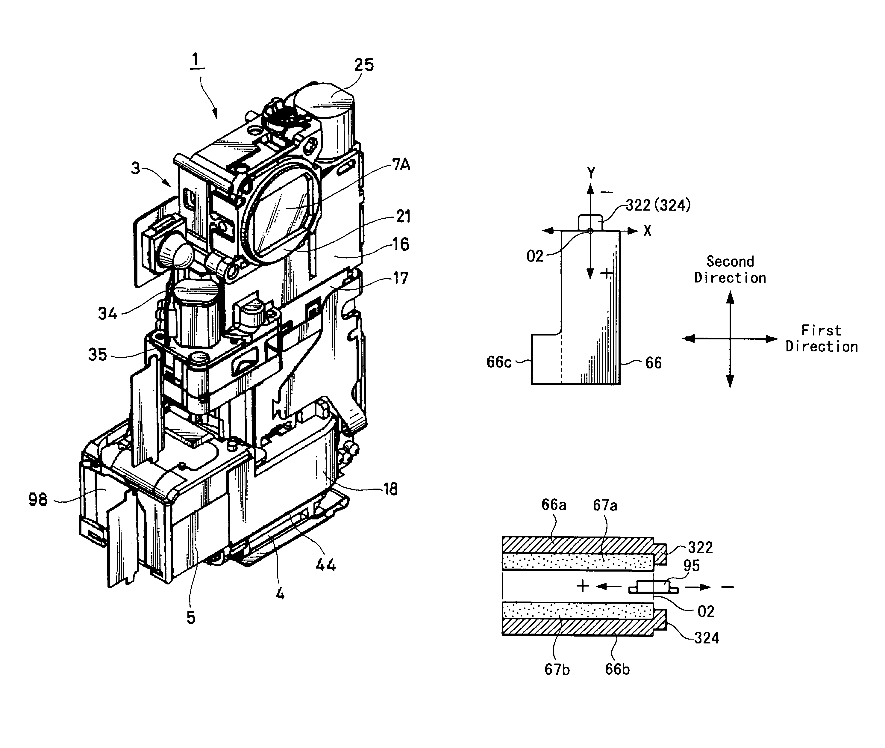
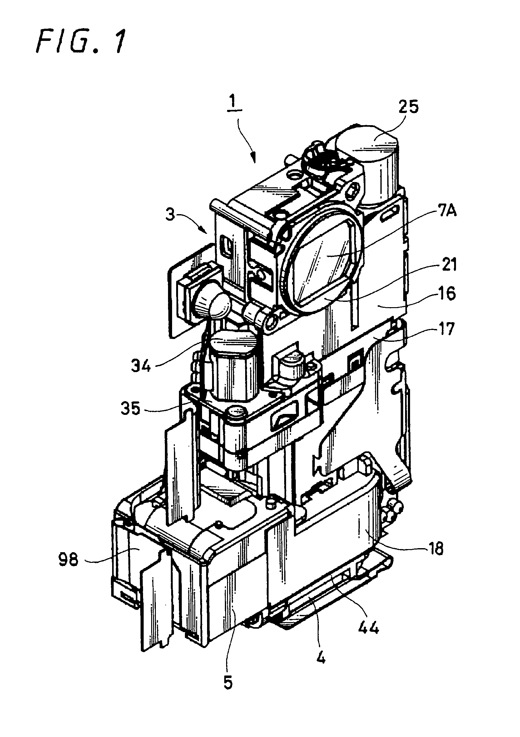
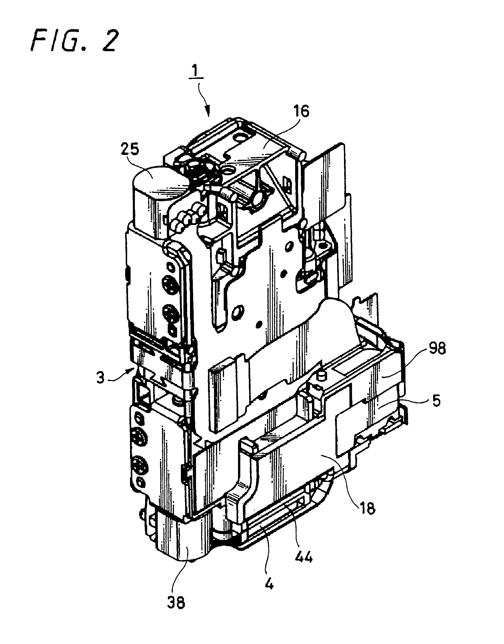
[0073]FIG. 1 is a perspective view showing a lens apparatus including an image stabilizer manufactured by the present invention from the front side. FIG. 2 is a perspective view showing the lens apparatus from the rear side. FIG. 3 is a front view thereof. FIG. 4 is a rear view thereof. FIG. 5 is a left-hand side elevational view thereof. FIG. 6 is a right-hand side elevational view thereof. FIG. 7 is a plan view thereof. FIG. 8 is a bottom view thereof. FIG. 9 is a cross-sectional view taken along the line M-M in FIG. 5. FIG. 10 is a cross-sectional view taken along the line N-N in FIG. 3. FIG. 11 is an exploded perspective view thereof. FIG. 12 is a diagram used to explain a lens system. FIG. 13 is an exploded perspective view of a digital still camera which shows a first example of an imager apparatus equipped with a lens apparatus including an image stabilizer manufactured by the present invention. FIG. 14 is a perspective view showing a digital still camera from the front side....

second embodiment

[0161]FIG. 33 is a block diagram showing a schematic arrangement of the digital still camera equipped with the image stabilizer 5 having the aforementioned arrangement and action. As shown in FIG. 33, this digital still camera 100A includes the lens apparatus 1 having the image stabilizer 5, a video recording / reproducing circuit unit 160 which plays a central role of the control apparatus, a built-in memory 161 including a program memory, and a data memory and other RAM and ROM to drive the video recording / reproducing circuit 160. There are also included a video signal processing unit 162 for processing a shot image and the like as a predetermined signal, a display apparatus 163 for displaying a shot image and the like, an external memory 164 for enlarging a storage capacity, a correcting lens control unit 165 for driving and controlling the image stabilizer 5 and the like.

[0162]The video recording / reproducing circuit unit 160 includes a calculating circuit having a microcomputer (C...


PUM


Abstract

An image stabilizer manufacturing method provides an image stabilizer which can steady blurry images produced by camera shake or vibration. One of the magnet and a coil supporting member are fixed to a moving frame. In the state in which an optical axis of a correcting lens is matched with an optical axis of a lens system, after first and second Hall elements were properly positioned at the position in which magnetic force received by both of the Hall elements becomes a reference value by moving the first and second Hall elements to first and second directions, the other of the magnet and the coil supporting member are fixed to a supporting frame.

Description

CROSS REFERENCES TO RELATED APPLICATIONS[0001]The present invention contains subject matter related to Japanese Patent Application JP 2005-201825 filed in the Japanese Patent Office on Jul. 11, 2005, the entire contents of which being incorporated herein by reference.BACKGROUND OF THE INVENTION[0002]1. Field of the Invention[0003]The present invention relates to a method of manufacturing an image stabilizer capable of stabilizing an image blurred from camera shake and the like by moving a correcting lens to the direction perpendicular to an optical axis of a lens system so that the optical axis of the correcting lens may coincide with the optical axis of the lens system when camera shake is produced. More particularly, the present invention relates to a method of manufacturing an image stabilizer in which a coil or a magnet constructing a part of a driver for moving a correcting lens can be properly positioned and fixed.[0004]2. Description of the Related Art[0005]In recent years, p...

Claims


Application Information

Patent Timeline
Patent Type & Authority Patents(United States)
IPC IPC(8): G02B7/02G02B5/08
CPCH04N5/23248H04N5/23287H04N5/23258H04N23/68H04N23/6812H04N23/687G03B5/04G03B5/06
Inventor TAKAHASHI, TATSUYUKI
Owner SONY CORP
Why Eureka
Try Eureka