Surgical ligation clip

a technology of ligation clips and clips, applied in the field of surgical ligation clips, can solve the problems of ligation clips, variable force applied by the clips to the vessel, and difficulty in removal or repositioning,

Active Publication Date: 2010-03-16
SURGICON INC +1
View PDF218 Cites 254 Cited by
  • Summary
  • Abstract
  • Description
  • Claims
  • Application Information

AI Technical Summary

Problems solved by technology

Such crushing action permanently deforms the clips making them difficult to remove or reposition.
Prior art surgical ligation clips have several inherent problems.
For example, the force applied by the clip to the vessel can be variable and inconsistent from one clip to the next because of the variation in crushing force applied to the clip by the user.
Further, prior art clips have a tendency to slip off the end of the blood vessel stub (i.e., perpendicular to the axis of the vessel) to which it has been applied because of the low coefficient of friction associated with the clip and lack of adequate restraining force provided by the clip.
A related problem found in the prior art is the fact that the ligation or restraining force offered by crushed clips vary along the length of the clip decreasing toward the open end.
Thus, the section of the vessel near the open end of the clip can be inadequately ligated.
This does not lend itself to clip appliers designed to pass through small 5 mm trocars.
To place a clip, the '573 patent uses an overly complex multi-stage trigger mechanism for actuating a clamping jaw and advancing the clip.
Secondly, the clip of the '573 patent provides for only a single point of contact of the clip on the vessel.
Thus, the side of the clip of the '269 patent which contains the single leg of the clamping arm may subject the vessel being ligated to greater shear than necessary.
The clip shown in FIG. 9 of the '269 patent can provide inadequate ligation for very small vessels that can be woven between the legs of the vessel support member and the leg of the clamping member because of spaces between these three legs.
Many clips of the prior art have an exposed free end which is small in dimension and can be caught or snagged on tissue during either the clip placement procedure or when in some circumstances the clip has to be removed.

Method used


Image

  • Surgical ligation clip
  • Surgical ligation clip
  • Surgical ligation clip

Examples


Embodiment Construction

[0027]Reference will now be made in detail to the present preferred embodiments of the invention, examples of which are illustrated in the accompanying drawings. Wherever possible, the same reference numbers will be used throughout the drawings to refer to the same or like parts.

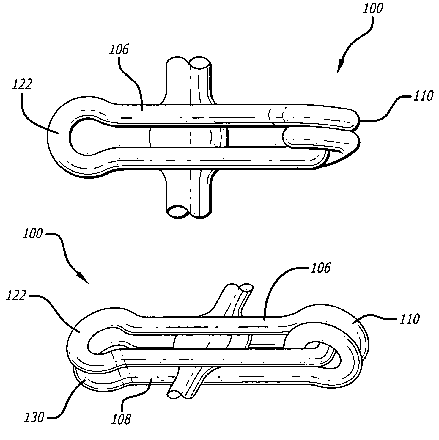
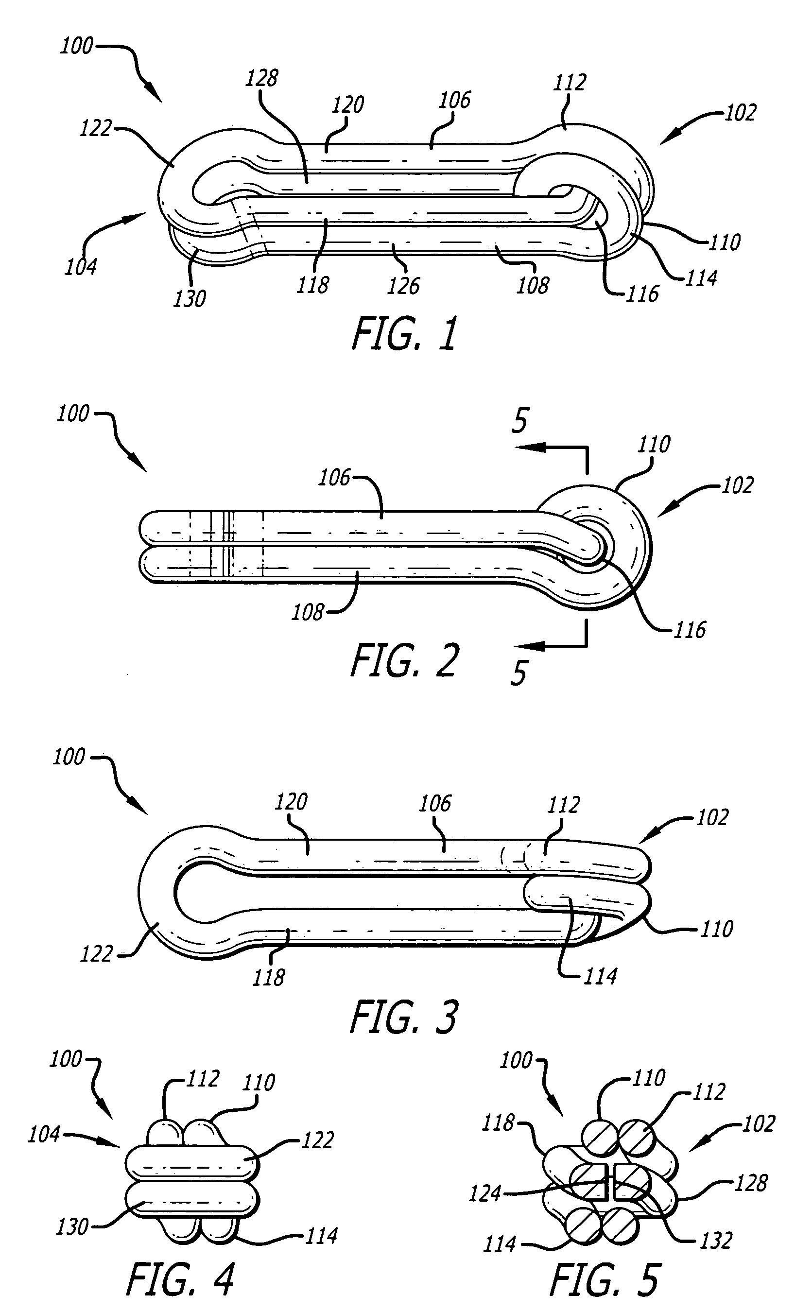
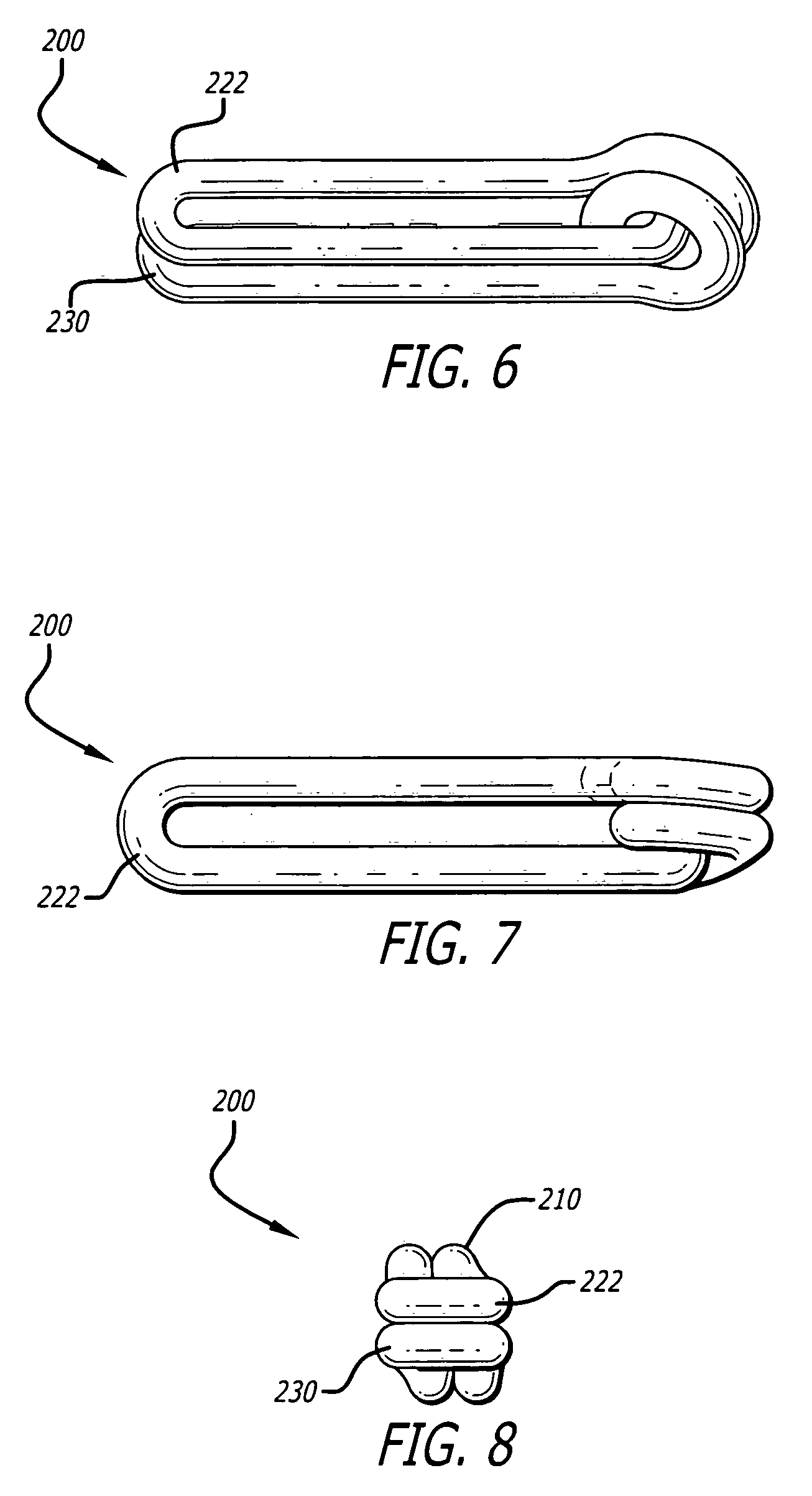
[0028]Referring now to the drawings and particularly to FIGS. 1 to 5, a surgical spring clip is shown and generally designated by the numeral 100. Clip 100 has a proximal end 102 and a distal end 104 opposite proximal end 102 along the mid-longitudinal axis of clip 100. Clip 100 includes an upper vessel support member 106 and a lower vessel support member 108. Upper and lower support members 106, 108 are joined together by a coil 110 at proximal end 102.

[0029]Coil 110 includes a first coil loop 112, a second coil loop 114, and an interior 116. First coil loop 112 is oriented generally parallel to the vertical longitudinal plane of clip 100. Second coil loop 114 is integrally joined to first coil loop 112 and...


PUM


Abstract

A surgical ligation clip for double ligating a vessel, duct or other fluid carrying structure and a method for double ligating such structure.

Description

RELATED APPLICATIONS[0001]This application claims the benefit of U.S. Provisional Application No. 60 / 425,521, filed Nov. 12, 2002, the disclosure of which is incorporated by reference herein.BACKGROUND OF THE INVENTION[0002]1. Field of the Invention[0003]The present invention relates generally to mechanical devices used in surgical procedures to obtain ligation or hemostasis and more particularly, to a ligation clip used during surgery to clamp vessels or ducts such as a cystic artery or cystic duct and thereby obtain ligation.[0004]2. Description of the Prior Art[0005]It will be appreciated by those skilled in the art that the use of ligation clips to control bleeding during surgical procedures is well known. As described, for example, in U.S. Pat. Nos. 4,976,722 and 4,979,950, prior art clips are generally formed of metal wire usually a titanium alloy having a U-shaped cross section. Such prior art clips often include a grooved pattern machined into the inner or clamping surfaces ...

Claims


Application Information

Patent Timeline
Patent Type & Authority Patents(United States)
IPC IPC(8): A61B17/08B42F1/02
CPCA61B17/083A61B17/1227Y10T24/44803Y10T24/44957Y10T24/205
Inventor SHIPP, JOHN I.
Owner SURGICON INC
Why Eureka
Try Eureka