[0016]It should be understood that the planar shape of the nanoflakes may provide a number of advantages. As a nonlimiting example, the planar shape may create greater surface area contact between adjacent nanoflakes that allows the dense film to form at a lower temperature and / or shorter time as compared to a film made from a precursor layer using an ink of spherical nanoparticles wherein the nanoparticles have a substantially similar material composition and the ink is otherwise substantially identical to the ink of the present invention. The planar shape of the nanoflakes may also create greater surface area contact between adjacent nanoflakes that allows the dense film to form at an annealing temperature at least 50 degrees C. less as compared to a film made from a precursor layer using an ink of spherical nanoparticles that is otherwise substantially identical to the ink of the present invention.
[0017]The planar shape of the nanoflakes may create greater surface area contact between adjacent nanoflakes relative to adjacent spherical nanoparticles and thus promotes increased atomic intermixing as compared to a film made from a precursor layer made from an ink of the present invention. The planar shape of the nanoflakes creates a higher packing density in the dense film as compared to a film made from a precursor layer made from an ink of spherical nanoparticles of the same composition that is otherwise substantially identical to the ink of the present invention.
[0020]The planar shape of the nanoflakes provides a material property to avoid rapid and / or preferential settling of the particles when forming the precursor layer. The planar shape of the nanoflakes provides a material property to avoid rapid and / or preferential settling of nanoflakes having different material compositions, when forming the precursor layer. The planar shape of the nanoflakes provides a material property to avoid rapid and / or preferential settling of nanoflakes having different particle sizes, when forming the precursor layer. The planar shape of the nanoflakes provides a material property to avoid grouping of nanoflakes in the ink and thus enables a finely dispersed solution of nanoflakes.
[0021]The planar shape of the nanoflakes provides a material property to avoid undesired grouping of nanoflakes of a particular class in the ink and thus enables an evenly dispersed solution of nanoflakes. The planar shape of the nanoflakes provides a material property to avoid undesired grouping of nanoflakes of a specific material composition in the ink and thus enables an evenly dispersed solution of nanoflakes. The planar shape of the nanoflakes provides a material property to avoid grouping of nanoflakes of a specific phase separation in the precursor layer resulting from the ink. The nanoflakes have a material property that reduces surface tension at interface between nanoflakes in the ink and a carrier fluid to improve dispersion quality.
[0022]In one embodiment of the present invention, the ink may be formulated by use of a low molecular weight dispersing agent whose inclusion is effective due to favorable interaction of the dispersing agent with the planar shape of the nanoflakes. The ink may be formulated by use of a carrier liquid and without a dispersing agent. The planar shape of the nanoflakes provides a material property to allow for a more even distribution of group IIIA material throughout in the dense film as compared to a film made from a precursor layer made from an ink of spherical nanoparticles that is otherwise substantially identical to the ink of the present invention. In another embodiment, the nanoflakes may be of random planar shape and / or a random size distribution.
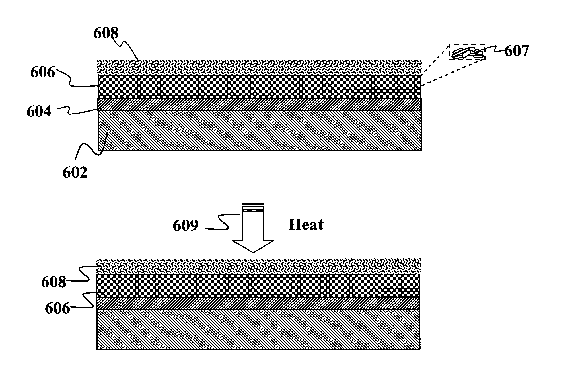
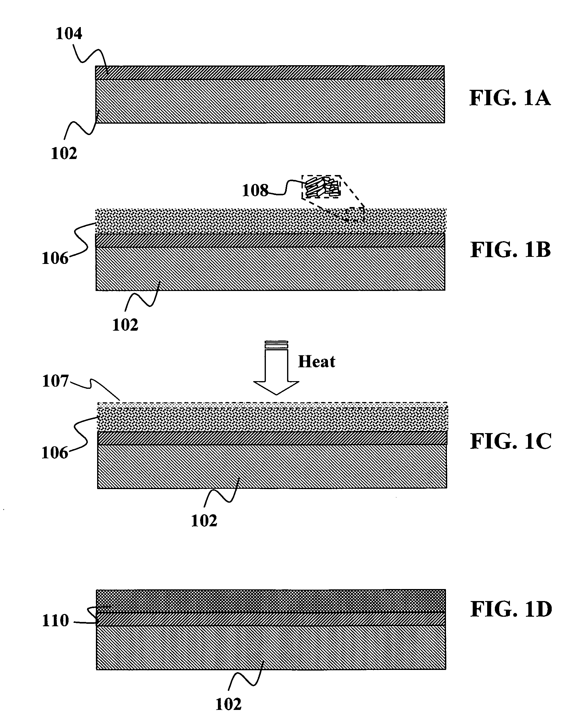
[0025]In one embodiment of the present invention, the coating step occurs at room temperature. The coating step may occur at atmospheric pressure. The method may further comprise depositing a film of selenium onto the dense film. The processing step may be accelerated via thermal processing techniques using at least one of the following: pulsed thermal processing, exposure to a laser beam, or heating via IR lamps, and / or similar or related methods. The processing may comprise of heating the precursor layer to a temperature greater than about 375° C. but less than a melting temperature of the substrate for a period of less than 15 minutes. The processing may comprise of heating the precursor layer to a temperature greater than about 375° C. but less than a melting temperature of the substrate for a period of 1 minute or less. In another embodiment of the present invention, processing may comprise of heating the precursor layer to an annealing temperature but less than a melting temperature of the substrate for a period of 1 minute or less. The suitable atmosphere may comprise of a hydrogen atmosphere. In another embodiment of the present invention, the suitable atmosphere comprises a nitrogen atmosphere. In yet another embodiment, the suitable atmosphere comprises a carbon monoxide atmosphere. The suitable atmosphere may be comprised of an atmosphere having less than about 10% hydrogen. The suitable atmosphere may be comprised of an atmosphere containing selenium. The suitable atmosphere may be comprised of an atmosphere of a non-oxygen chalcogen. In one embodiment of the present invention, the suitable atmosphere may comprise of a selenium atmosphere providing a partial pressure greater than or equal to vapor pressure of selenium in the precursor layer. In another embodiment, the suitable atmosphere may comprise of a non-oxygen atmosphere containing chalcogen vapor at a partial pressure of the chalcogen greater than or equal to a vapor pressure of the chalcogen at the processing temperature and processing pressure to minimize loss of chalcogen from the precursor layer, wherein the processing pressure is a non-vacuum pressure. In yet another embodiment, the chalcogen atmosphere may be used with one or more binary chalcogenides (in any shape or form) at a partial pressure of the chalcogen greater than or equal to a vapor pressure of the chalcogen at the processing temperature and processing pressure to minimize loss of chalcogen from the precursor layer, wherein optionally, the processing pressure is a non-vacuum pressure.

