Trailer hitch receiver lock

a receiver lock and hitch technology, applied in the field of trailer security locks, can solve the problems of insufficient space between the cylinder lock and the collar, the point cannot be effectively gripped by a jaw-type tool in the effort to break the lock, and the thickness of the collar is too thick for cutting with the bolt cutter

Inactive Publication Date: 2010-05-11
LOVENBERG JOEL L
View PDF1 Cites 10 Cited by
  • Summary
  • Abstract
  • Description
  • Claims
  • Application Information

AI Technical Summary

Benefits of technology

[0025]The primary object of the present invention is to provide a trailer hitch ball receiver lock which prevents attachment of the trailer hitch ball receiver to a vehicle having a trailer hitch ball and which cannot be easily removed from the trailer hitch ball receiver to insure security for trailers by making the trailer unable to be towed, moved or stolen by eliminating access to the tow-ball receiver part of the trailer.
[0030]The trailer security lock of the present invention provides a more secure lock for trailers because the lock collar part of the lock is welded to the trailer ball receiver becoming part of the trailer Itself. This security lock also few more deterrents to prevent prying, cutting or drilling. For greater security, the lock cylinder and lock shaft spin freely inside a hardened collar, preventing prying or drilling of the lock or sawing of the lock shaft. The lock ball is only slightly smaller in diameter than the ball receiver so that the lock ball spins within the ball receiver but a toll will not fit therebetween to prevent drilling, cutting, or prying, making it an extremely secure lock. The trailer security lock of the present invention is fabricated of a hardened metal alloy in different sizes to accommodate different size trailer ball receivers.

Problems solved by technology

The collar is too thick for cutting with bolt cutters.
There is not sufficient room between the cylinder lock and collar or between the lock ball and the ball receiver to pry the cylinder lock or the lock ball away from the collar and ball receiver.
A small downwardly tapered conical point extending downwardly from the bottom of the lock ball serves as a grip for installing the lock ball up into the ball receiver, but the point cannot be gripped effectively by a jaw type tool in efforts to break the lock.

Method used


Image

  • Trailer hitch receiver lock
  • Trailer hitch receiver lock

Examples


Embodiment Construction

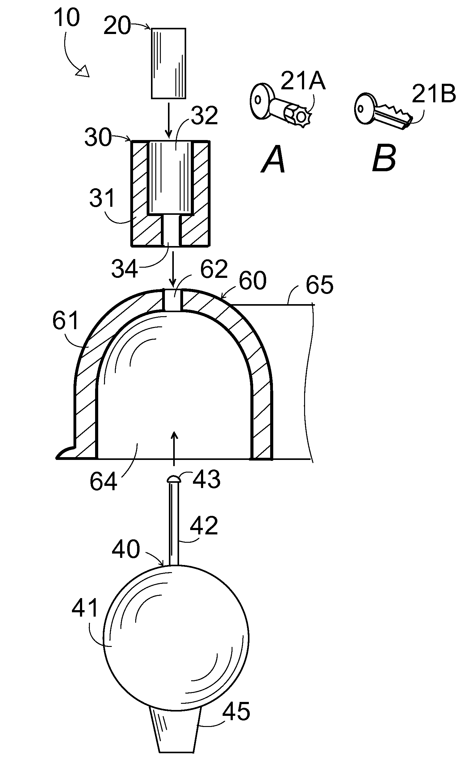
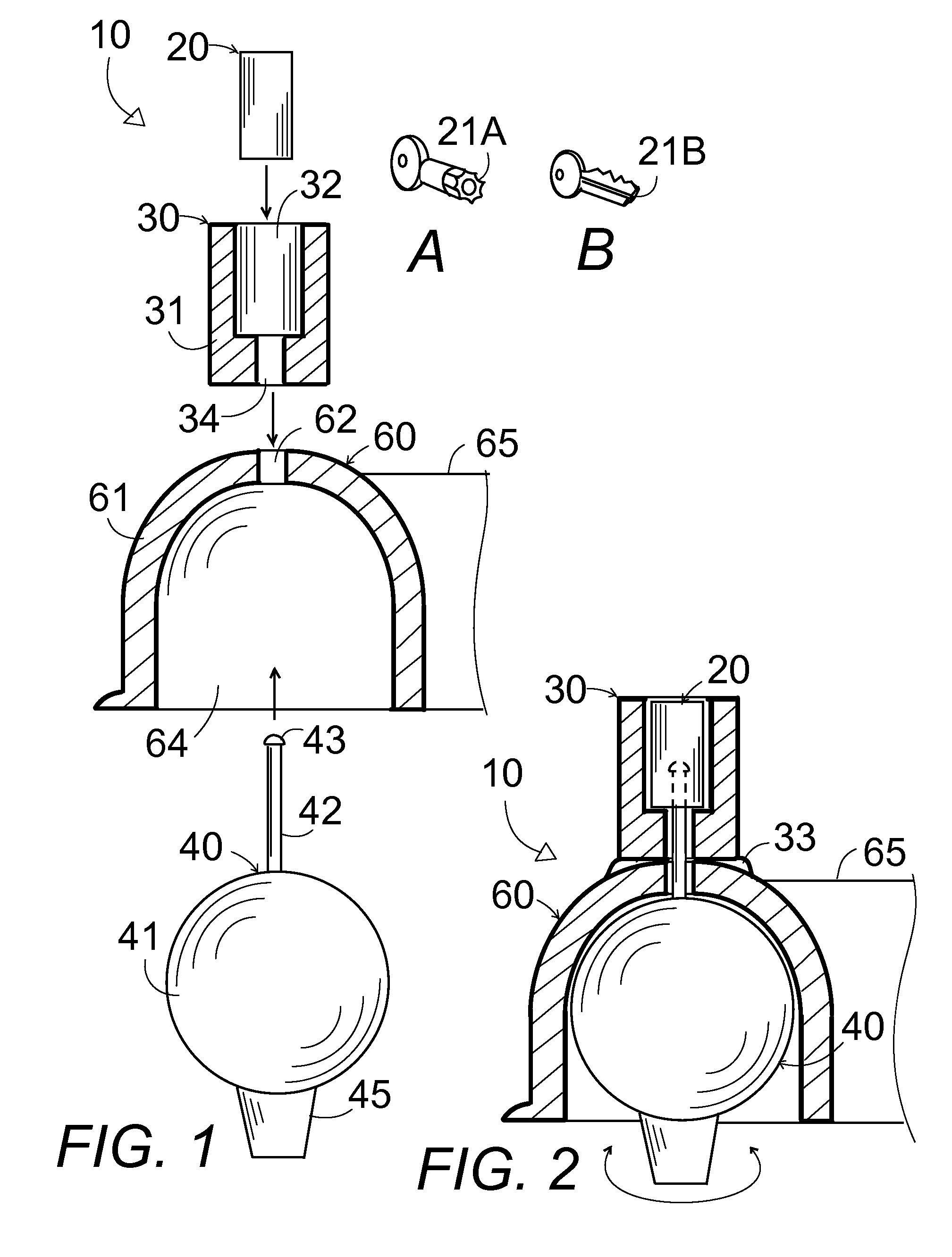
[0034]In FIGS. 1 and 2, a trailer hitch ball receiver security lock device 10 comprises a lock ball component 40 having a steel sphere 41 fitting within a trailer hitch ball receiver 60 and a lock shaft 42 with an end lock knob 43 extending up through a top center hole 62 in the ball receiver through a thick walled bottom opening 34 in the lock collar 30 into a cylinder lock 20 in a top opening 32 in the lock collar 30 which is welded to the top of the ball receiver and having the cylinder lock 20 fitting down into the lock collar 30 locking onto the lock post 42 so that the cylinder lock 20, steel sphere 41, and lock shaft 42 are secured to the ball receiver 60 and lock collar 30 and spin freely therein to prevent drilling the lock.

[0035]In FIGS. 1 and 2, the lock collar 30 is welded by a weld 33 onto a top of the trailer hitch ball receiver 60. The lock collar 30 comprises a hardened steel cylinder having a top cylindrical opening 32 through a vertical centerline of the collar for...


PUM


Abstract

A freely pivoting lock ball fits within a trailer hitch ball receiver. A top lock shaft on the ball extends up through a hole in the top of the ball receiver into a lock collar welded to the top of the ball receiver. A cylinder lock fits into a top opening in the lock collar over the lock shaft to lock the lock ball within the ball receiver to prevent theft by towing the trailer with a conventional towing hitch ball. The cylinder lock and lock ball spin freely within the ball receiver and collar to prevent drilling or sawing the lock. There is no room between the cylinder lock and collar or between the ball lock and ball receiver to pry them loose. The lock collar is too thick for cutting with a bolt cutter.

Description

CROSS-REFERENCE TO RELATED APPLICATIONS[0001]The present utility patent application claims the benefit of provisional application No. 60 / 975,285 filed Sep. 26, 2007.STATEMENT REGARDING FEDERALLY SPONSORED RESEARCH OR DEVELOPMENT[0002]Not applicable.THE NAMES OF THE PARTIES TO A JOINT RESEARCH OR DEVELOPMENT[0003]Not applicable.BACKGROUND OF THE INVENTION[0004]1. Field of the Invention[0005]The present invention relates to trailer security locks, and in particular to a trailer security lock having a freely pivoting lock ball within a trailer hitch ball receiver with a lock shaft extending up through a hole in the top of the ball receiver into a collar welded to the top of the ball receiver and having a cylinder lock fitting into the collar over the lock shaft to lock the lock ball within the ball receiver to prevent theft by towing the trailer with a conventional towing hitch ball, wherein the cylinder lock and lock ball pivot freely within the ball receiver and collar to prevent dri...

Claims


Application Information

Patent Timeline
Patent Type & Authority Patents(United States)
IPC IPC(8): E05B67/38
CPCB60D1/60Y10T70/5982
Inventor LOVENBERG, JOEL L
Owner LOVENBERG JOEL L
Why Eureka
Try Eureka