Pneumatic bioreactor

a bioreactor and pneumatic technology, applied in the field of biopharmaceutical, can solve the problems of large capital investment for construction, inflexible changes in manufactuwheel schedules and production capacities, and long lead times, and achieve the effect of efficient and thorough mixing

Inactive Publication Date: 2010-05-11
PBS BIOTECH INC
View PDF83 Cites 7 Cited by
  • Summary
  • Abstract
  • Description
  • Claims
  • Application Information

AI Technical Summary

Benefits of technology

[0006]The present invention is directed to a bioreactor with mixing apparatus including a rotational mixer in a containment vessel capable of efficiently and thoroughly mixing solutions without contamination. Large scale disposable units are also contemplated. The bioreactor includes a gas supply driving a rotational mixer having buoyancy driven mixing cavities.

Problems solved by technology

However, shortages of global biomanufactuwheel capacity are anticipated in the foreseeable future.
Manufactuwheel facilities with conventional stainless bioreactors, however, require large capital investments for construction, high maintenance costs, long lead times, and inflexibilities for changes in manufactuwheel schedules and production capacities.
The procedure of cleaning and sterilization requires a significant amount of time and resources.
The problems with sterilization are compounded by the need to monitor and to validate each cleaning step prior to reuse for production of biopharmaceutical products.
However, the mixing technology of the current disposable bioreactor system has limitations in terms of scalability to sizes beyond 200 liters and the expense of large scale units.
While several methods of mixing liquid in disposable bioreactors have been proposed in recent years, none of them provide efficient mixing in large scale (greater than 1000 liters) without expensive operating machinery.

Method used


Image

  • Pneumatic bioreactor
  • Pneumatic bioreactor
  • Pneumatic bioreactor

Examples


Embodiment Construction

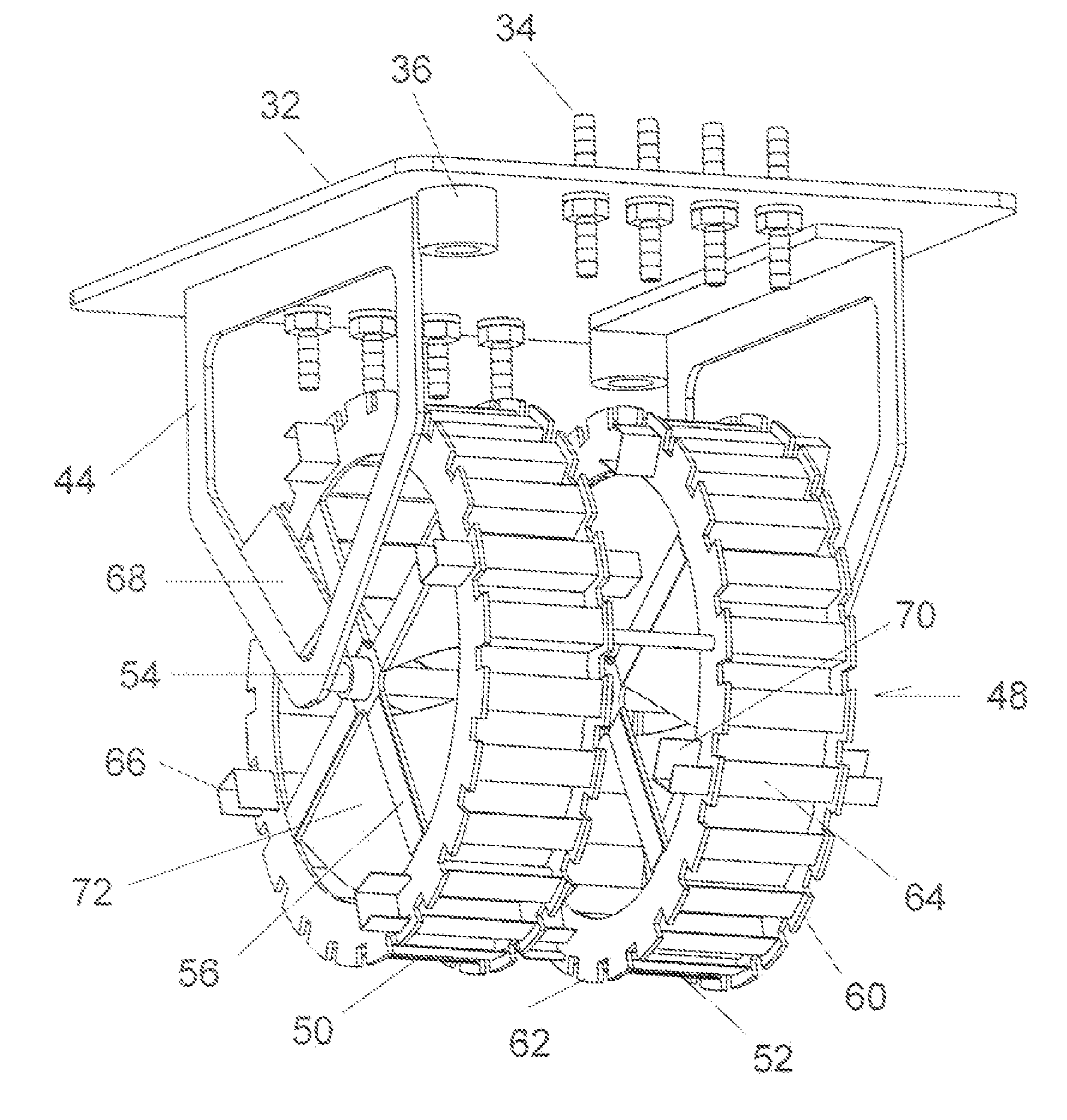
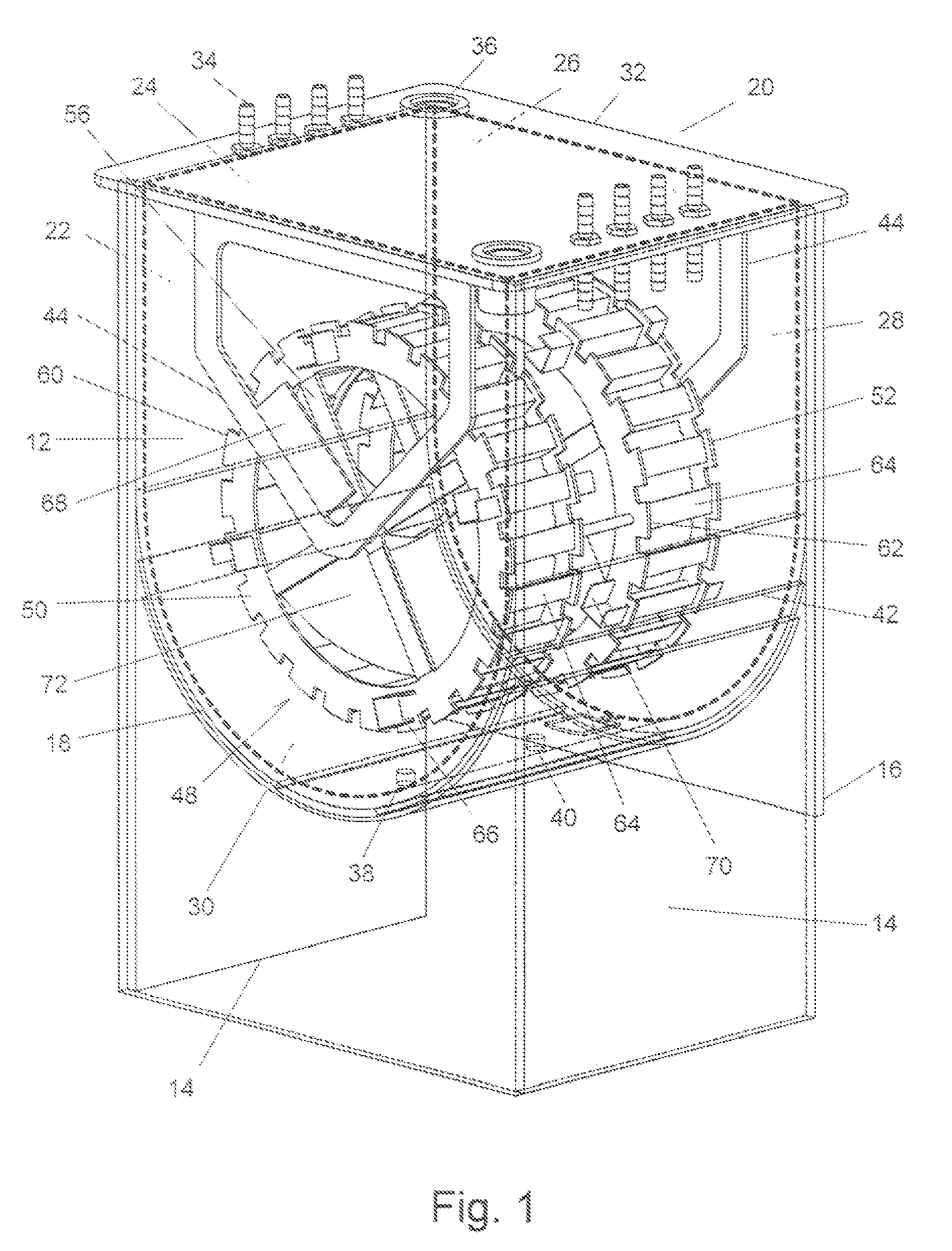
[0016]Turning in detail to the drawings, a bioreactor positioned in a housing, generally designated 10, is illustrated. The housing 10 is structural and preferably made of stainless steel to include a housing front 12, housing sides 14 and a housing back 16. The housing back 16 does not extend fully to the floor or other support in order that access may be had to the underside of the bioreactor. The housing 10 includes a housing bottom 18 which extends from the housing sides 14 in a semi-cylindrical curve above the base of the housing 10. One of the front 12 or back 16 may act as a door to facilitate access to the interior of the housing 10.

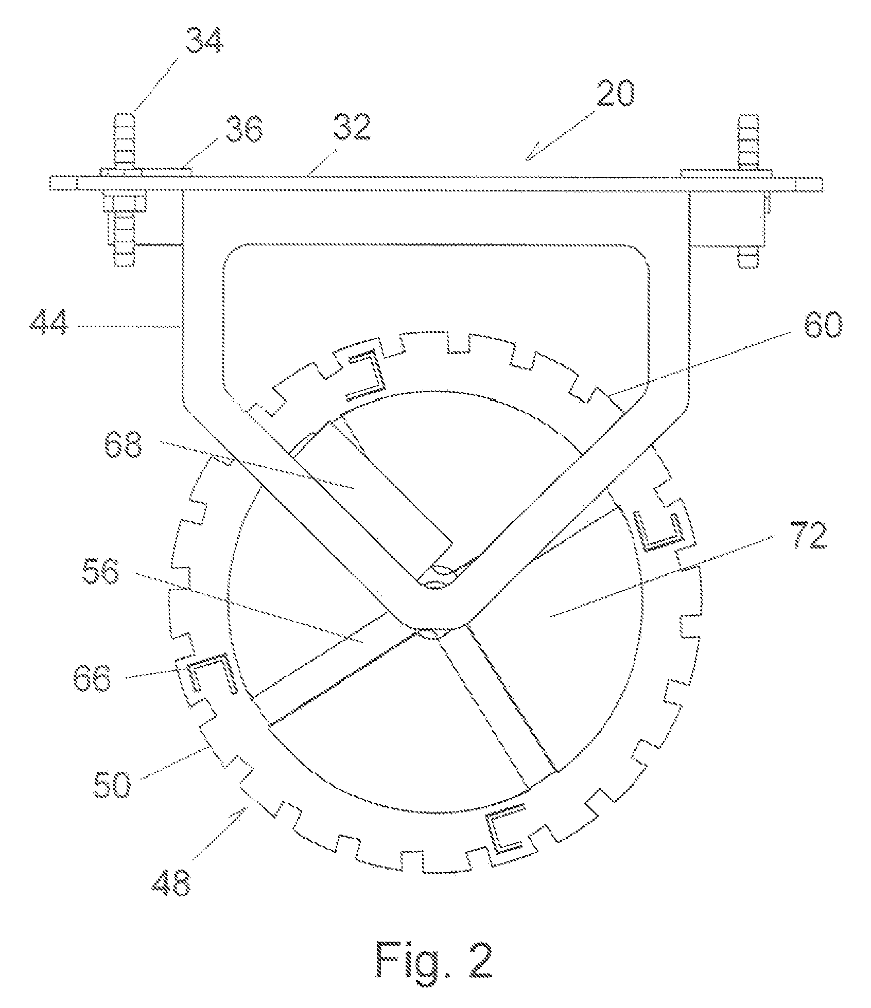
[0017]The bioreactor includes a containment vessel, generally designated 20, defined by four vessel sides 22, 24, 26, 28, a semi-cylindrical vessel bottom 30 and a vessel top 32. Two of the vessel sides 24, 28 which are opposed each include a semicircular end. The other two vessel sides 22, 28 join with the semi-cylindrical vessel bottom 30 to fo...


PUM

PropertyMeasurementUnit
timeaaaaaaaaaa
flexibilityaaaaaaaaaa
sizesaaaaaaaaaa

Abstract

A pneumatic bioreactor having a containment vessel which includes a semi-cylindrical concavity defined by the vessel bottom. A mixing apparatus includes a rotational mixer rotatably mounted within the containment vessel about a horizontal axis. The rotational mixer has buoyancy-driven mixing cavities which are fed by a gas supply beneath the rotational mixer. The mixing apparatus extends into the semi-cylindrical concavity to substantially fill that concavity. The rotational mixer is divided into two wheels with outer paddles extending axially outwardly and inner paddles extending axially inwardly on either side of each wheel. Blades between the outer and inner paddles form impellers in the wheels to induce axial flow through the wheels in opposite directions. Stationary baffles fixed relative to the containment vessel are inclined toward the rotational mixer in the direction of rotation. The containment vessel may be of film and supported by a structural housing also having a semi-cylindrical concavity defined by the housing bottom.

Description

BACKGROUND OF THE INVENTION[0001]The field of the present invention is bioreactors with mixing.[0002]Efforts of biopharmaceutical companies to discover new biological drugs have increased exponentially duwheel the past decade. Most biological drugs are produced by cell culture or microbial fermentation processes which require sterile bioreactors and an aseptic culture environment. However, shortages of global biomanufactuwheel capacity are anticipated in the foreseeable future. An increasing number of biological drug candidates are in development. Stwheelent testing, validation, and thorough documentation of process for each drug candidate are required by FDA to ensure consistency of the drug quality used for clinical trials to the market. Further, production needs will increase as such new drugs are introduced to the market. Bioreactors have also been used for cultivation of microbial organisms for production of various biological or chemical products in the beverage and biotechnol...

Claims


Application Information

Patent Timeline
Patent Type & Authority Patents(United States)
IPC IPC(8): C12M1/06
CPCB01F3/04588B01F7/00308B01F7/00916C12M27/20C12M27/06B01F7/04B01F15/005B01F15/00545B01F23/2332B01F27/11252B01F27/55B01F27/70B01F35/32045B01F35/32015
Inventor ZEIKUS, J. GREGORYKIM, KYUNGNAMPOST, THOMAS A.JOHNSON, KEITH E.
Owner PBS BIOTECH INC
Why Eureka
Try Eureka