Electrical connector with a tongue with two sets of contacts

a technology of electric connectors and tongues, applied in the direction of coupling device connections, coupling protective earth/shielding arrangements, electrical apparatus, etc., can solve the problems of easy destruction of usb receptacles, consumers cannot use these normal usb interfaces conveniently, and standard usb 2.0 cannot meet the requirements of many electric devices

Active Publication Date: 2010-05-18
HON HAI PRECISION IND CO LTD
View PDF6 Cites 25 Cited by
  • Summary
  • Abstract
  • Description
  • Claims
  • Application Information

AI Technical Summary

Benefits of technology

[0008]According to the present invention, an electrical connector comprises: an insulative housing comprising a base portion, the base portion having a front face, a top face and a mounting face opposite to the top face, the insulative housing having a tongue extending forwardly from the front face, the tongue having a left face and a right face; a metal shell covering the insulative housing and defining a receiving space with the insulative housing, the metal shell comprising a left wall and a right wall; and a plurality of contacts retained in the insulative housing, each contact having a contact portion extending to the left face of the tongue and a soldering portion extending out of the mounting face. The space between the left face and the left wall is larger than that between the right face and the right wall.

Problems solved by technology

As a miniaturized development of electronic industry, the standard USB 2.0 can not satisfied the requirement of many electric devices because of a large mounting space thereof.
However, whether standard USB receptacle or upright USB receptacle, there are many consumers can not use these normal USB interfaces conveniently and usually insert a corresponding plug conversely which destroys the USB receptacle easily.

Method used


Image

  • Electrical connector with a tongue with two sets of contacts
  • Electrical connector with a tongue with two sets of contacts
  • Electrical connector with a tongue with two sets of contacts

Examples


Embodiment Construction

[0020]In the following description, numerous specific details are set forth to provide a thorough understanding of the present invention. However, it will be obvious to those skilled in the art that the present invention may be practiced without such specific details. In other instances, well-known circuits have been shown in block diagram form in order not to obscure the present invention in unnecessary detail. For the most part, details concerning timing considerations and the like have been omitted inasmuch as such details are not necessary to obtain a complete understanding of the present invention and are within the skills of persons of ordinary skill in the relevant art.

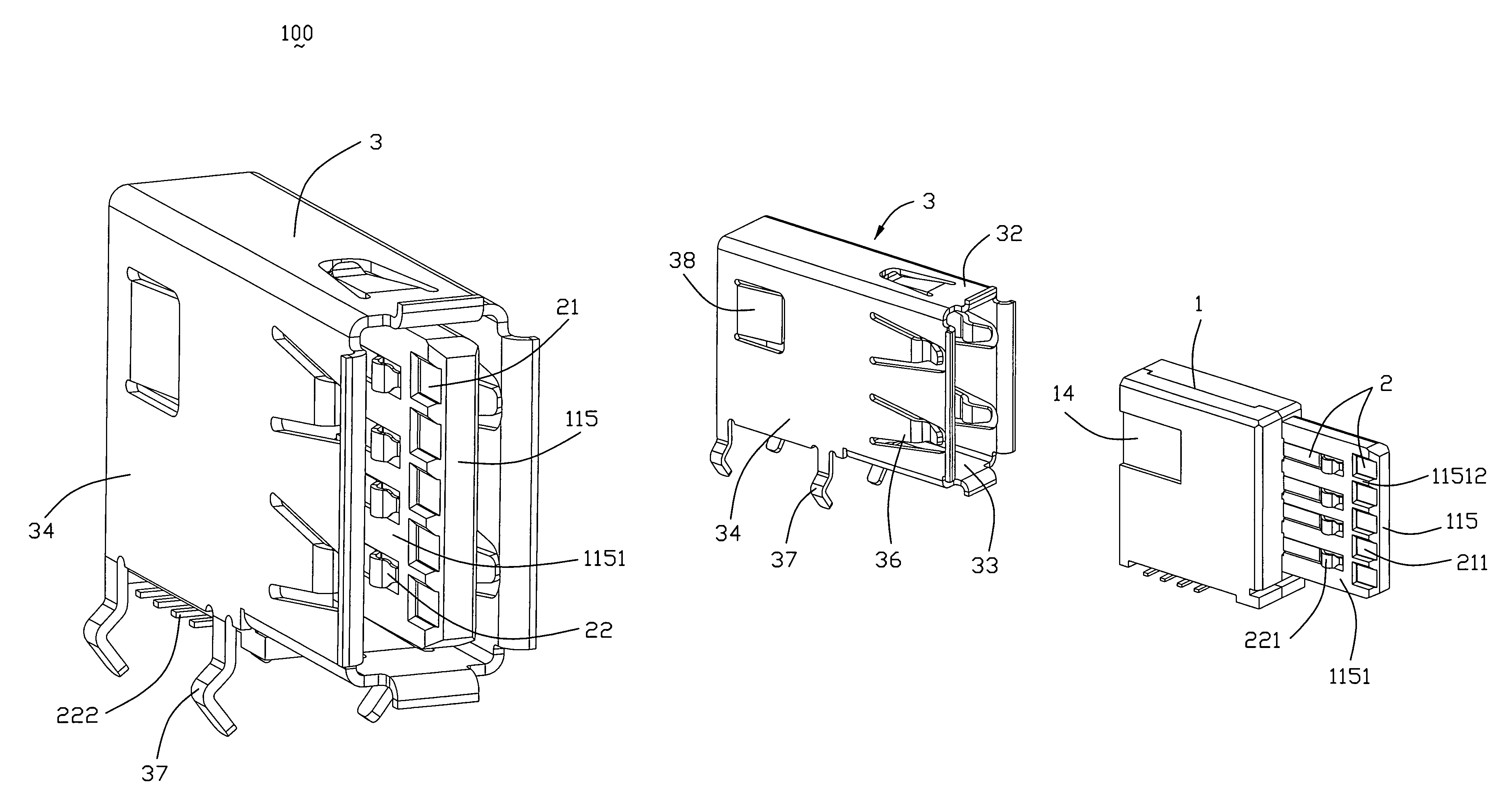
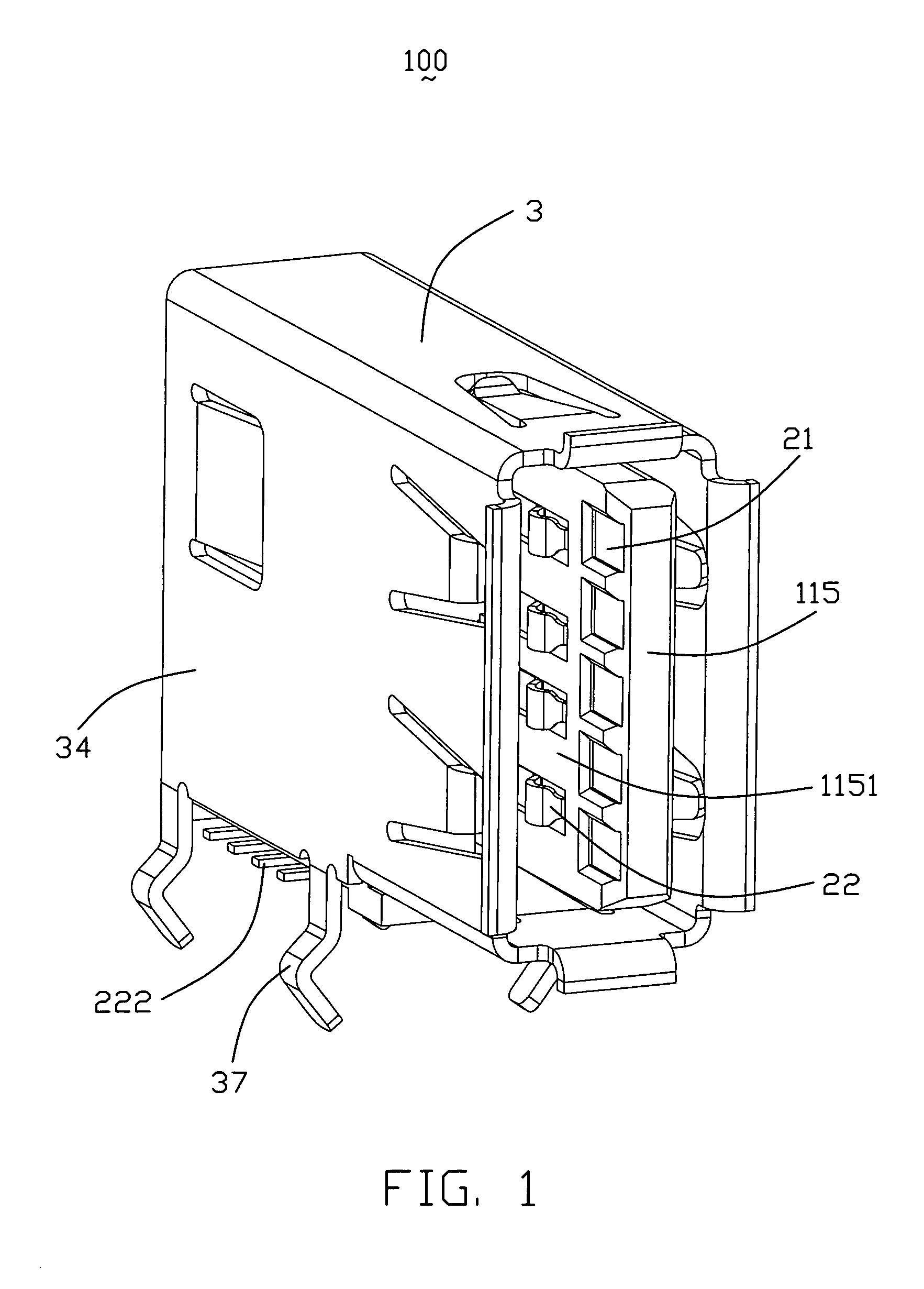
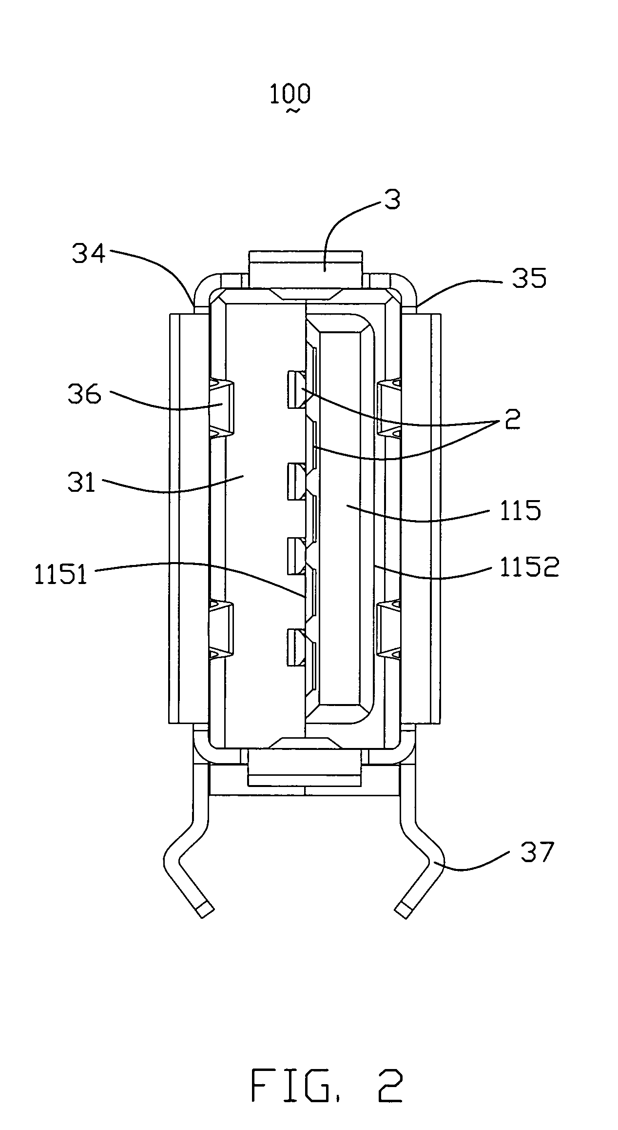
[0021]Referring to FIGS. 1-6, an electrical connector 100 according to a first embodiment of the present invention is disclosed. The electrical connector 100 comprises an insulative housing 1, a plurality of contacts 2 retained in the insulative housing 1, and a metal shell 3 covering the insulative housing 1.

[...


PUM


Abstract

An electrical connector (100) includes an insulative housing (1), a plurality of contacts (2) retained in the insulative housing (1) and a metal shell (3). The insulative housing (1) has a base portion (111). The base portion (111) has a front face (112), a top face (113) and a mounting face (114) opposite to the top face (113). The insulative housing (1) has a tongue (115) extending forwardly from the front face (112). The tongue (115) has a left face (1151) and a right face (1152). The metal shell (3) comprises a left wall (34) and a right wall (35). Each contact (2) has a contact portion (211, 221) extending to the left face (1151) of the tongue (115). The space between the left face (1151) and the left wall (34) is larger than that between the right face (1152) and the right wall (35).

Description

BACKGROUND OF THE INVENTION[0001]1. Field of the Invention[0002]The present invention relates to an electrical connector, and more particularly to electrical connectors with a tongue.[0003]2. Description of Related Art[0004]Universal Serial Bus (USB) is used widely in variety electronic devices as a standard and simple interface. The standard USB 2.0 receptacle comprises an insulative housing, a plurality of contacts received in the insulative housing and a metal shell covering the insulative housing. The insulative housing has a base and a tongue extending levelly and forwardly from the base. The metal shell has a top wall and a bottom wall which are parallel to the tongue. The space between an upper face of the tongue and the top wall is smaller than that between a lower face of the tongue and the bottom wall. Each contact has a contact portion extending to the lower face of the tongue.[0005]As a miniaturized development of electronic industry, the standard USB 2.0 can not satisfi...

Claims


Application Information

Patent Timeline
Patent Type & Authority Patents(United States)
IPC IPC(8): H01R13/648
CPCH01R13/642
Inventor HE, JIA-YONGZHENG, QI-SHENGGU, HAO
Owner HON HAI PRECISION IND CO LTD
Why Eureka
Try Eureka