Multiple coil staple and staple applier

a technology of multi-coil staples and appliers, which is applied in the direction of surgical staples, paper/cardboard containers, prostheses, etc., to achieve the effect of increasing the width

Inactive Publication Date: 2010-05-25
TYCO HEALTHCARE GRP LP
View PDF39 Cites 1310 Cited by
  • Summary
  • Abstract
  • Description
  • Claims
  • Application Information

AI Technical Summary

Problems solved by technology

One problem associated with known staples and staple appliers is that the staples are dimensioned or sized to fasten tissue segments of a given tissue thickness or fasten tissue segments within a predetermined narrow range of thicknesses.

Method used


Image

  • Multiple coil staple and staple applier
  • Multiple coil staple and staple applier
  • Multiple coil staple and staple applier

Examples


Embodiment Construction

[0031]Embodiments of the presently disclosed multiple coil staple and / or staple applier will now be described in detail with reference to the drawings wherein like numerals designate identical or corresponding elements in each of the several views.

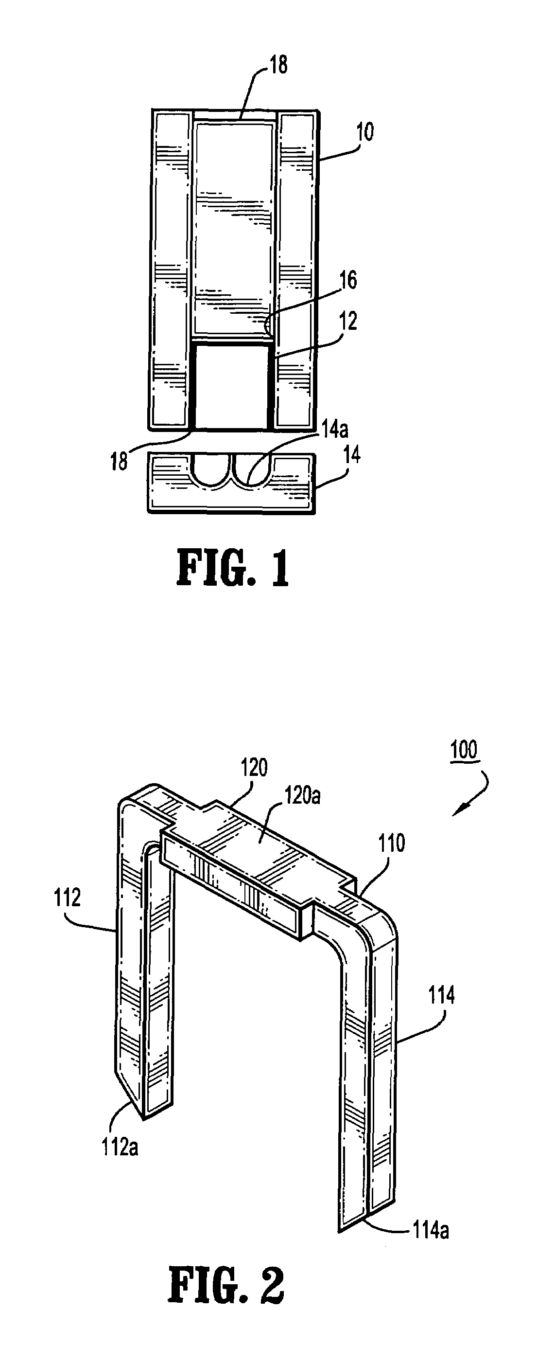
[0032]Referring to FIG. 1, a surgical stapler typically includes a housing 10, one or more staples 12 and an anvil 14 having a staple deforming surface 14a. Housing 10 which may be configured as a cartridge can include at least one staple receiving slot 16 dimensioned to slidably receive a staple 12. In many staplers, a pusher or driver 18 is slidably positioned within slot 16 behind a respective staple 12. An actuator (not shown) is provided to advance pusher 18 through slot 16 and eject staple 12 from an outlet side 20 of cartridge 10 into deforming surface or anvil pocket 14a of anvil 14. Deforming surface 14a can be configured to deform a staple into a desired configuration, e.g., a B-configuration.

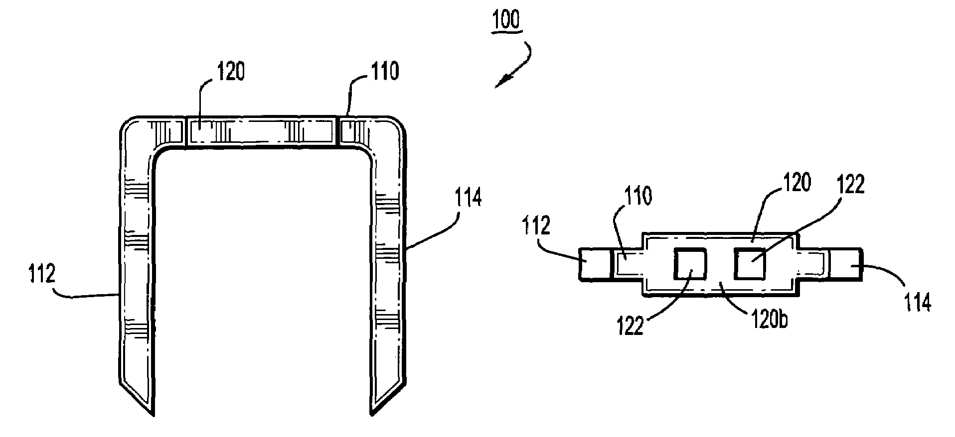
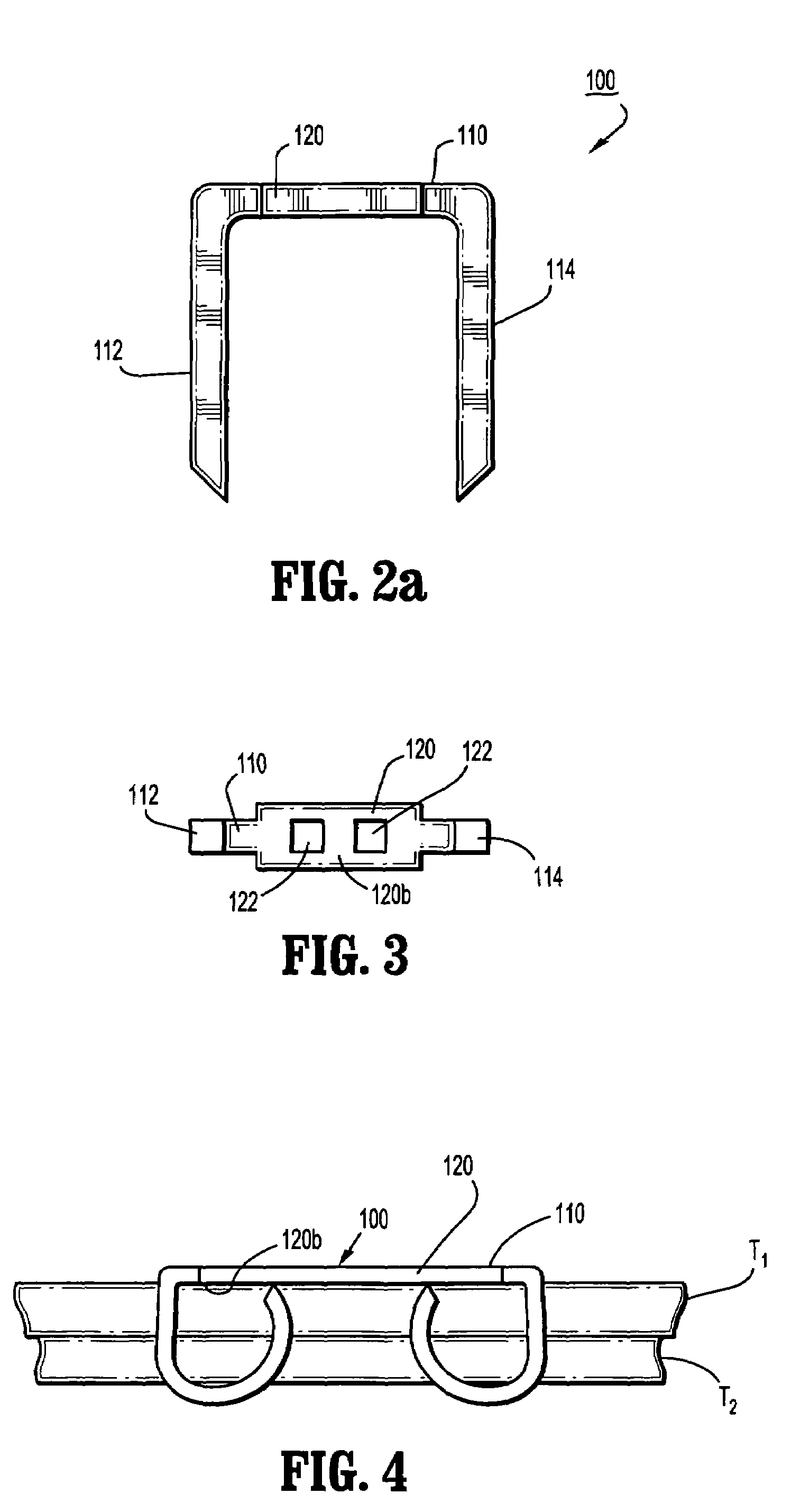
[0033]Referring to FIGS. 2-4, in one ...


PUM

PropertyMeasurementUnit
widthaaaaaaaaaa
angleaaaaaaaaaa
thicknessesaaaaaaaaaa

Abstract

A multiple coil staple is provided which includes a backspan and a pair of spaced legs. The backspan includes one or more pockets configured to induce coiling of the legs of the staple. A multiple coil staple applier is also provided which includes a pusher having a distal face defining a staple engagement surface and one or more staple deforming pockets. Each staple deforming pocket is configured to induce coiling of the legs of a staple. The multiple coil staple and staple applier facilitate joining of tissues having wider ranges of thicknesses using a single size staple.

Description

CROSS REFERENCE TO RELATED APPLICATION[0001]This application claims the benefit of and priority to U.S. Provisional Patent Application Ser. No. 60 / 686,773 entitled “MULTIPLE COIL STAPLE AND STAPLE APPLIER,” which was filed on Jun. 2, 2005, the entire contents of which are hereby incorporated by reference herein.BACKGROUND[0002]1. Technical Field[0003]The present disclosure relates to a fastener and a fastener applier. More particularly, the present disclosure relates to a staple and / or staple applier with structure for curling or coiling staple legs to facilitate joining of tissues having varying thicknesses.[0004]2. Background of Related Art[0005]Surgical staples and stapling instruments are well known in the surgical arts and have become critical to many life saving surgical procedures. The use of stapling instruments for applying staples to join tissue or tissue segments in a fast and efficient manner has obviated the time consuming step of manually suturing tissue or tissue segm...

Claims


Application Information

Patent Timeline
Patent Type & Authority Patents(United States)
IPC IPC(8): A61B17/068
CPCA61B17/0644A61B17/0686B25C5/0257A61B17/0682Y10S227/902A61B2017/0498A61B2017/0725A61B2017/07264A61B17/0684
Inventor VIOLA, FRANK J.GRESHAM, RICHARD D.BLIER, KENMERTEN, PAULSAPIENTE, JOSEPHHOLSTEN, HENRY E.HEINRICH, RUSSELL
Owner TYCO HEALTHCARE GRP LP
Why Eureka
Try Eureka