Stabilizing holder for sensory device

a technology for stabilizing holder and sensory device, which is applied in the direction of transducer details, instruments, electrical transducers, etc., can solve the problems of microphone stand vibration transfer through the support and vertical shaft of the microphone stand, unwanted activation of sound capture devices attached to the microphone, and microphone to produce unwanted signals

Active Publication Date: 2010-05-25
KELLY JEFFERY
View PDF67 Cites 27 Cited by
  • Summary
  • Abstract
  • Description
  • Claims
  • Application Information

AI Technical Summary

Benefits of technology

[0015]One embodiment of the present invention provides an advantageous device for installing and utilizing a sensory device, microphone or other device in conjunction with a drum or series of drums.
[0045]Another embodiment of the present invention provides means for installing the main mounting unit which will not dramatically change the actual sound of the drum.

Problems solved by technology

These stands also can transfer vibrations through the support and vertical shaft of the microphone stand.
These vibrations can cause the microphone to produce an unwanted signal.
The vibrations can also cause unwanted activation of sound capturing devices attached to the microphone.
Another disadvantage is that limited space may also present a problem for placement of the numerous microphone stands needed to amplify various drums at once, as in the case of a drum set.
This placement creates a trip hazard for other musicians.
This placement also increases the likelihood of accidentally displacing the microphone due to the outwardly extending boom and counter-weight assembly.
The additional space required to place the microphone stand on the floor in front of the bass drum, also requires additional floor space in front of the bass drum which may not be available, as in the case of the drums being set up on an elevated platform.
Another disadvantage is that the time and effort spent in assembling the above devices, outfitting them with the microphones, achieving the proper placement and alignment of the microphone, and connecting them to the amplification system is often considerable.
For example, the mounting bracket has the likelihood of transferring vibrations of the drum shell induced by the percussion of the musician's striking instrument against the striking surface of the drumhead, creating a possibly unwanted signal being sent by the microphone to the amplification system.
Other disadvantages are that the aforementioned effort is also a semi-permanent installation, thereby making removal and replacement of the system somewhat of an inconvenience.
At least one disadvantage of this embodiment is that the installation of the connection device may be undesirable to some owners and players of the instrument.
Being a rigid mounting bracket, the amount of adjustment range from the inside of the drum shell to the microphone itself is restricted and minimal at best.
For example, the coil springs may create unwanted audio effects due to the individual coils of the springs striking one another.
Another disadvantage is that the effort disclosed by Webber also requires the use of the drum baffle element to utilize the microphone holder, which eliminates the choice of the individual to use only the microphone mount by itself.
For example, this method may increase the risk of damage to the microphone by the impact of the drummer's striking instrument.
This effort also requires additional time and effort to prepare the system for use.

Method used


Image

  • Stabilizing holder for sensory device
  • Stabilizing holder for sensory device
  • Stabilizing holder for sensory device

Examples


Embodiment Construction

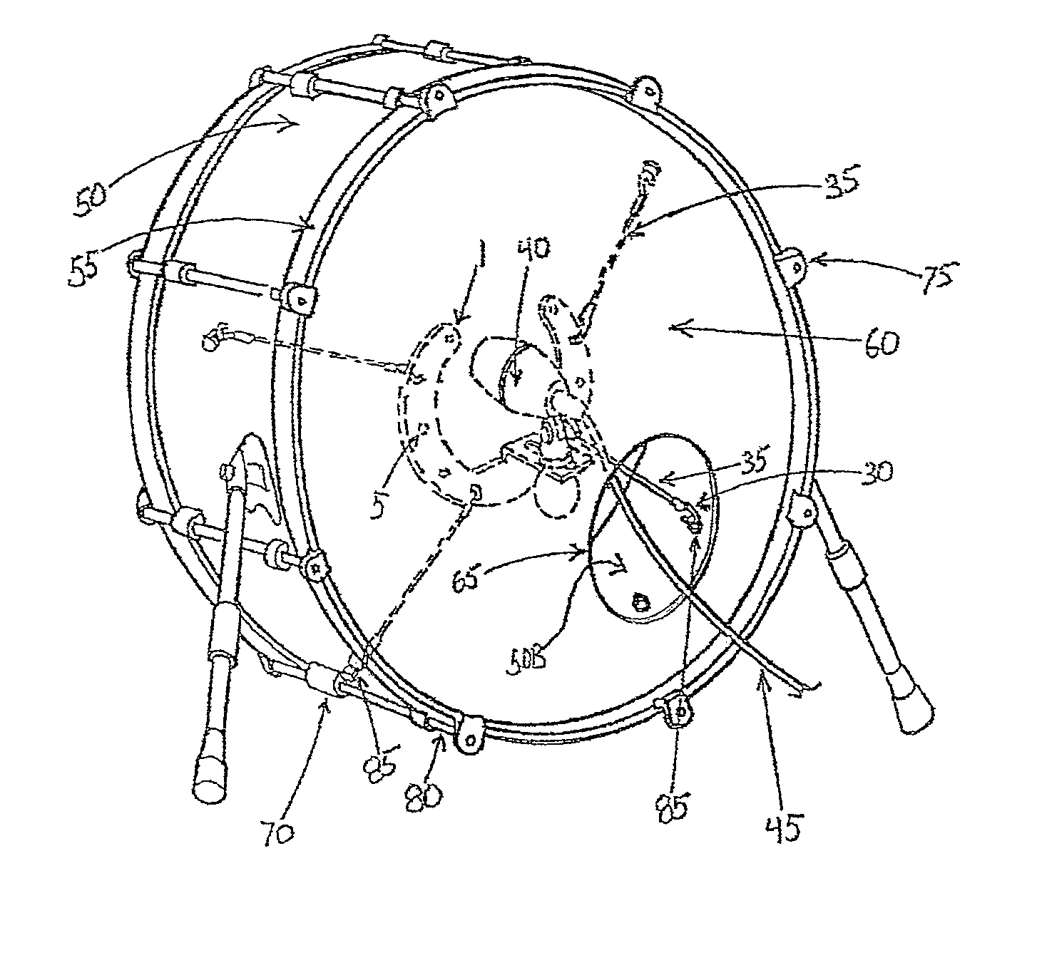
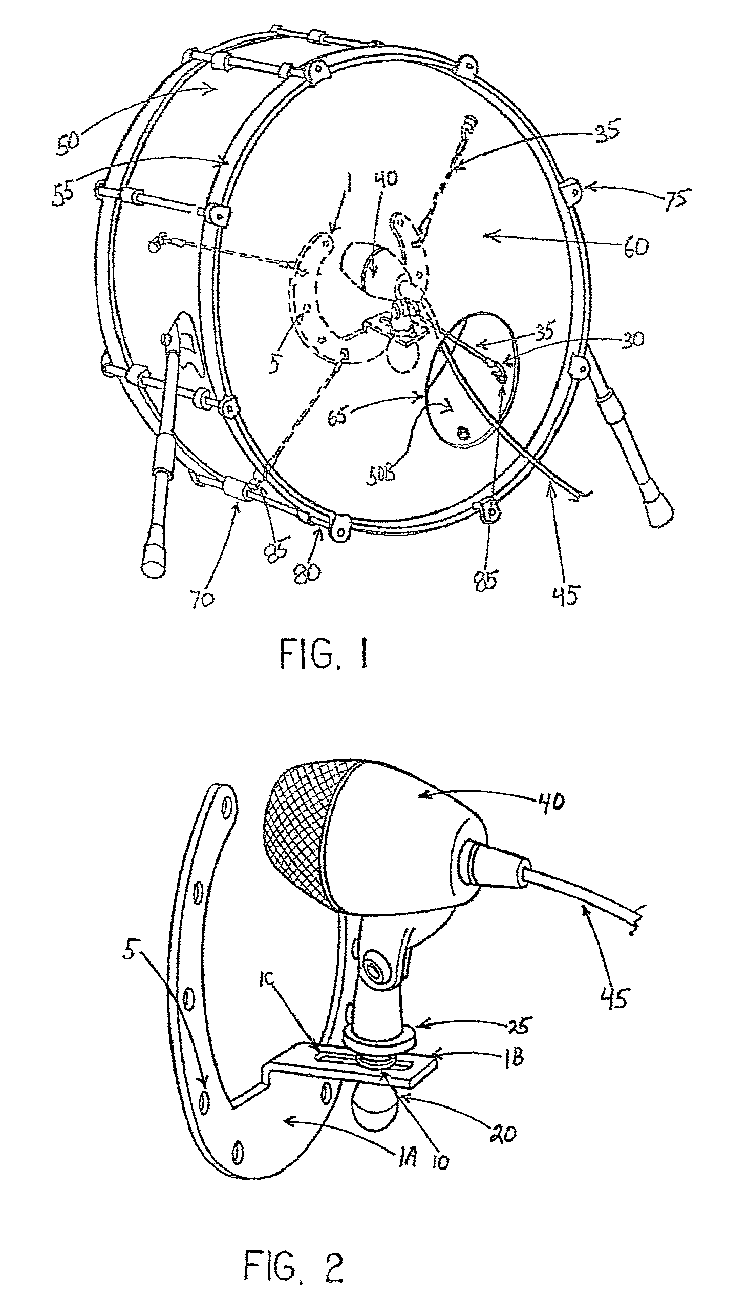
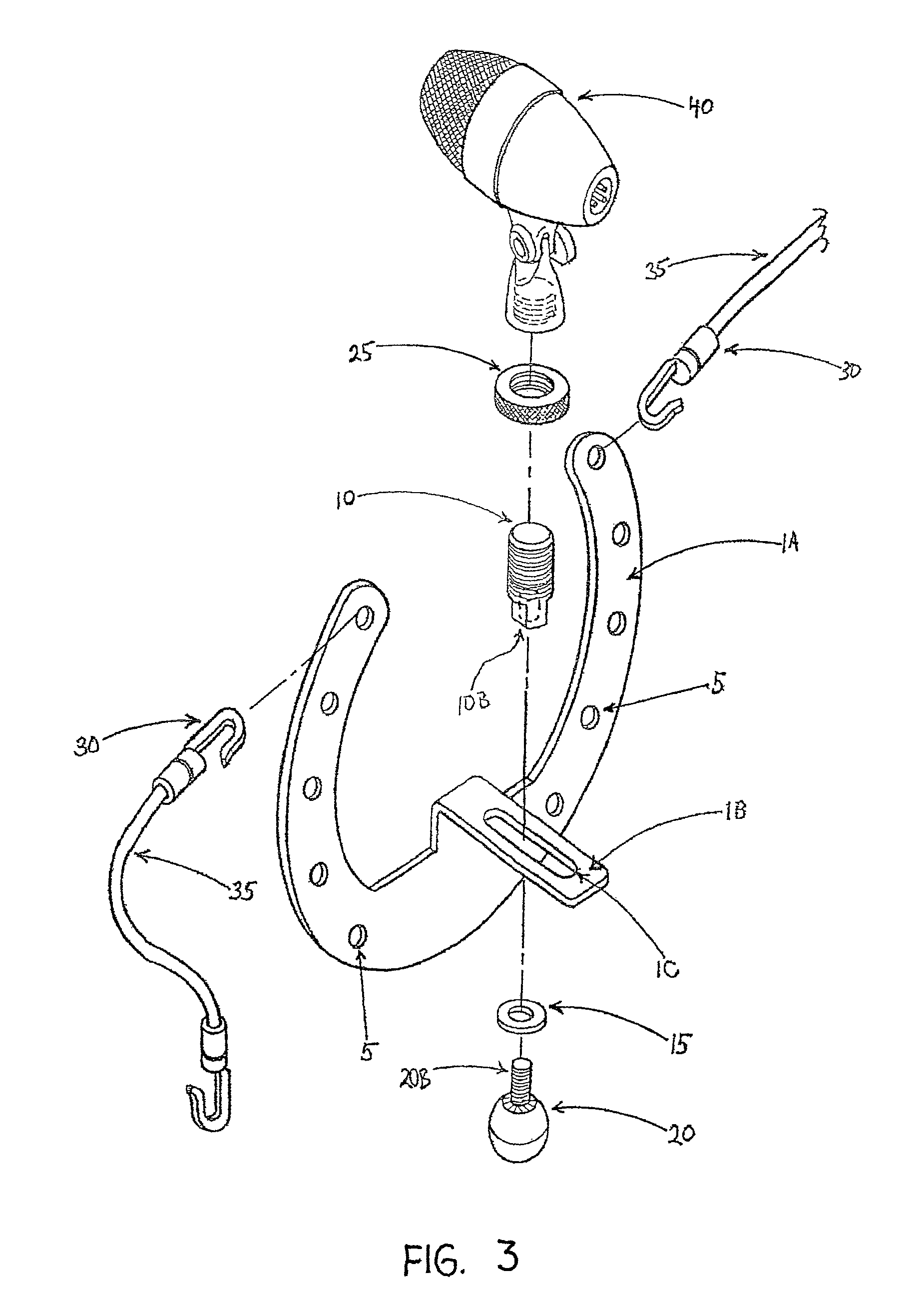
[0065]FIG. 1 illustrates the present invention in one of its embodiments. The rigid central main mounting unit 1 may be constructed of any material with substantial strength to withstand the outward pressures exerted by the elastomer support cords 35. For example, the main mounting unit 1 may comprise aluminum, metal, steel, plastics, composite materials such as carbon fiber, strong woods and laminates of woods, or a combination thereof. A plurality of holes 5 are created around the outside edge 1A of the main mounting unit 1 to accept the attachment hooks or loops located on the ends of the support cords. The main mounting unit 1, with the sensory device 40 attached, is housed inside the drum shell 50. The main mounting unit 1 is supported inside the drum shell 50 by means of the elastomer cords 35. One end of the elastomer cords 35 engages the main mounting unit 1 by utilizing a hook 30 which is passed through the user's choice of holes 5 present in plurality around the circumfere...


PUM


Abstract

A holder for mounting a sensory device to a musical instrument includes a bracket having a plurality of first connector elements, a locking mechanism for fixing the sensory device to the bracket; and a plurality of hanger members. The bracket supports the sensory device and each of the hanger members connects at least one of the first connector elements to at least one of a plurality of second connector elements attached to the musical instrument. The second connector elements being spaced apart from each other and the hanger members hold the bracket at a predetermined position.

Description

CROSS-REFERENCE TO RELATED APPLICATION[0001]This application claims the benefit of and priority to U.S. Provisional Patent Application No. 60 / 805,702, filed Jun. 23, 2006, entitled STABILIZING HOLDER FOR SENSORY DEVICE, which document is hereby incorporated by reference to the extent permitted by law.BACKGROUND OF THE INVENTION[0002]The present invention relates generally to holding devices, and more particularly to an improved holding device used for holding a sensory device, such as microphones, for use on musical instruments such as drums.[0003]Acoustical drums have long been an integral part in musical groups and performances.[0004]Various types of sensory devices have been affixed to acoustical drums to measure, enhance, record, and / or monitor different aspects (e.g., sound, images, temperature, humidity, light-level, etc.) associated with an acoustical drum or the environment corresponding to the acoustical drum.[0005]For example, in some cases, it is desirable to electrically...

Claims


Application Information

Patent Timeline
Patent Type & Authority Patents(United States)
IPC IPC(8): G10D9/00
CPCH04R1/083
Inventor KELLY, JEFFERY
Owner KELLY JEFFERY
Why Eureka
Try Eureka