Recreational rope turning device and associated method

Inactive Publication Date: 2010-06-01
FOSTER TOMMIE +1
View PDF16 Cites 16 Cited by
  • Summary
  • Abstract
  • Description
  • Claims
  • Application Information

AI Technical Summary

Benefits of technology

[0032]Each of the arms preferably includes a resilient spring member concentrically situated thereabout and configured in such a manner that the spring member compresses along a rectilinear path defined parallel to the rear brace and a longitudinal length of the arms when the rope tension levels are above the maximum rope tension level, respectively. Each arm may further include a locking member removably coupled to a medial end of each arm, respectively, for pr

Problems solved by technology

With two ropes twirling, the skipper went “Double Dutch”, and the skipping grew more athletic and more complicated.
Unfortunately, this prior art reference does not enable a user to disengage the rope from the motor after the rope is caught in the user's

Method used


Image

  • Recreational rope turning device and associated method
  • Recreational rope turning device and associated method
  • Recreational rope turning device and associated method

Examples


Embodiment Construction

[0050]The present invention will now be described more fully hereinafter with reference to the accompanying drawings, in which a preferred embodiment of the invention is shown. This invention may, however, be embodied in many different forms and should not be construed as limited to the embodiment set forth herein. Rather, this embodiment is provided so that this application will be thorough and complete, and will fully convey the true scope of the invention to those skilled in the art. Like numbers refer to like elements throughout the figures.

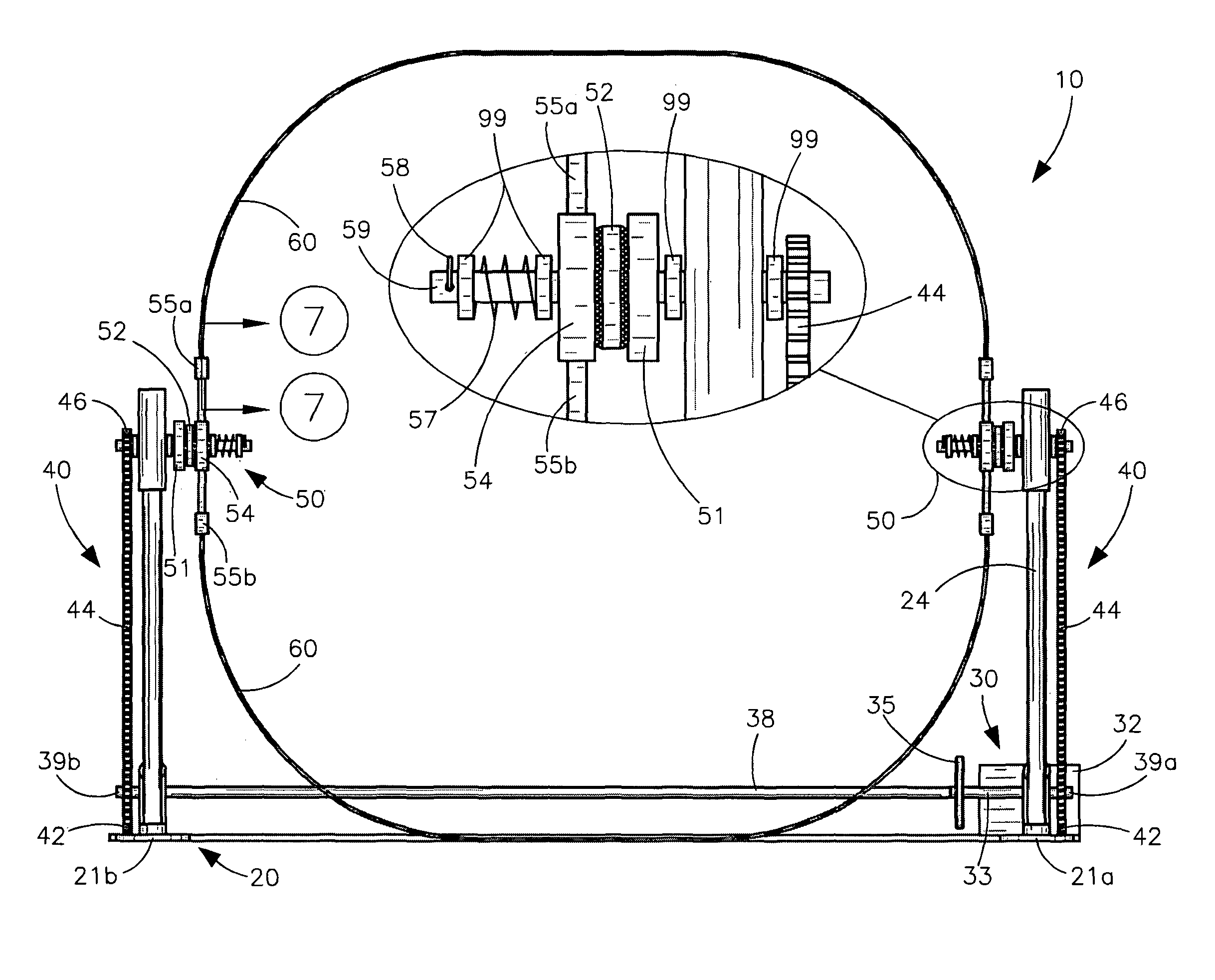
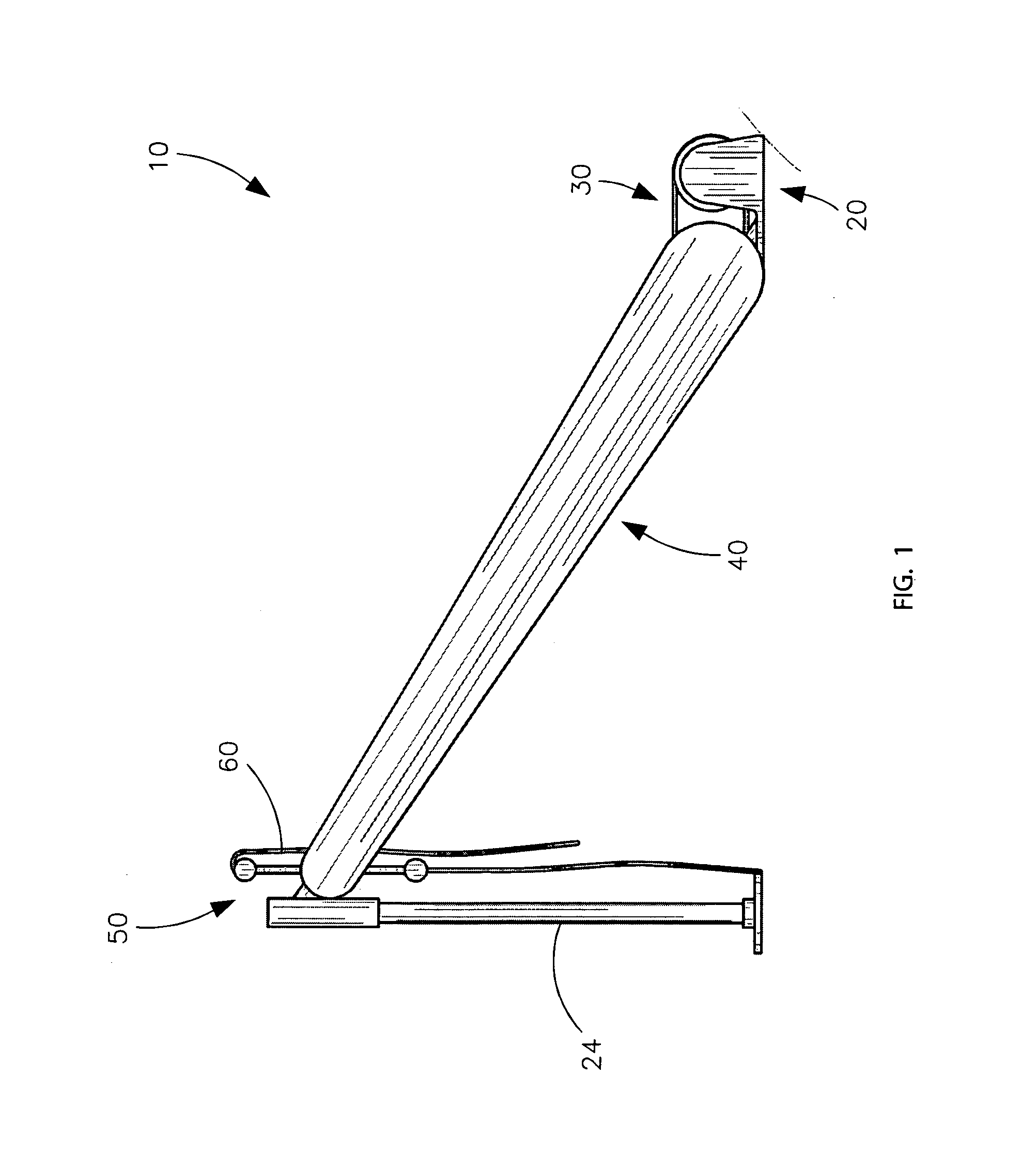
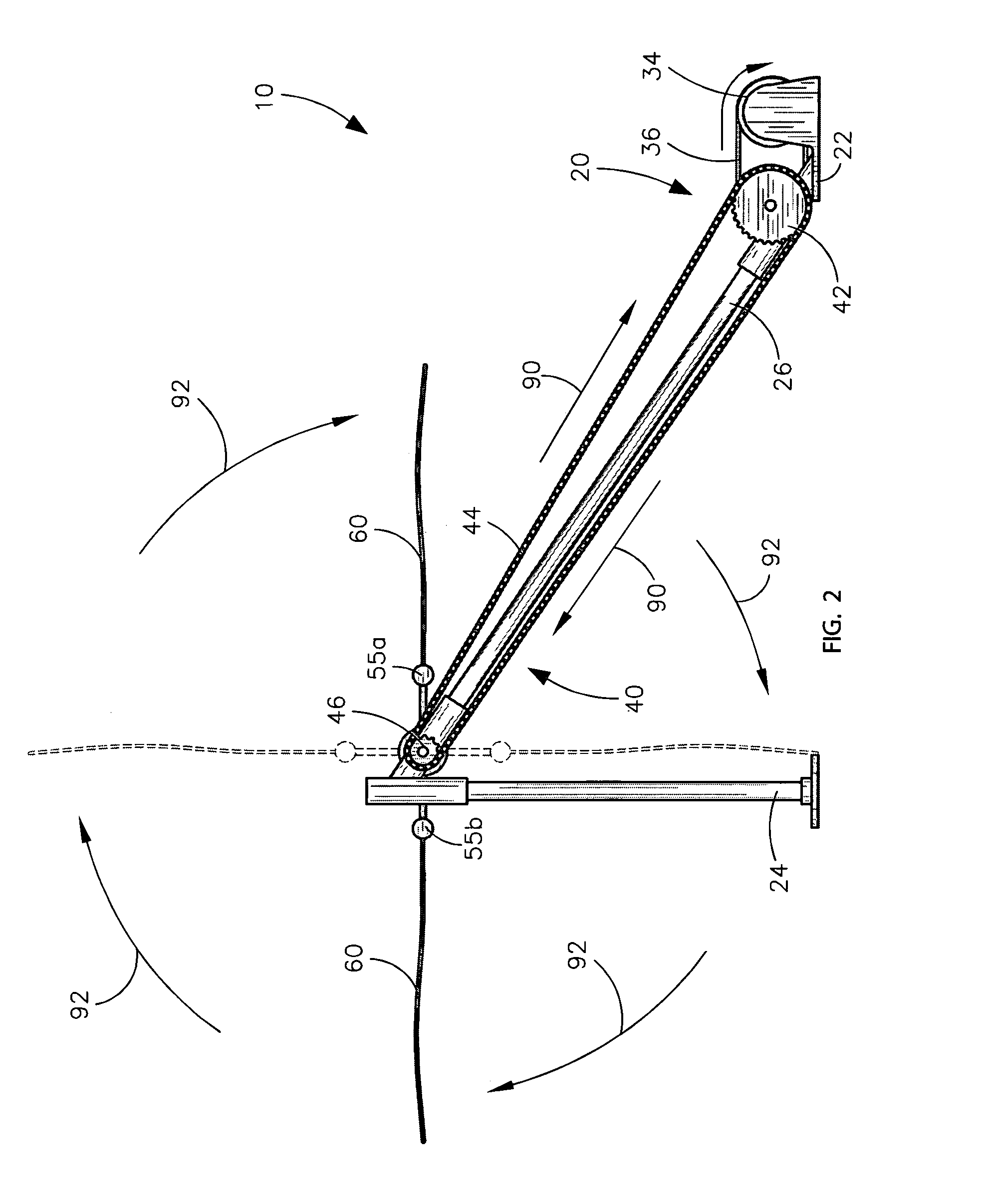
[0051]The device of this invention is referred to generally in FIGS. 1-8 by the reference numeral 10 and is intended to provide an automated jump rope exercising device. It should be understood that the automated jump rope exercising device 10 may be used to allow a single user to practice solo rope jumping activities in many different environments.

[0052]Referring initially to FIGS. 1-5, the automated jump rope exercising device 10 may includ...


PUM


Abstract

An automated jump rope exercising device includes a frame, a power operated primary drive pulley system, and a plurality of auxiliary driven pulley systems that may be operably coupled to the primary drive pulley system. Each of the auxiliary driven pulley systems may be simultaneously rotated in a first synchronous path during operating conditions based upon input from the primary drive pulley. The device may further include a plurality of arms that may be conjoined to the auxiliary driven pulley systems respectively. A plurality of ropes may be detachably anchored to the arms, and each of the ropes may be simultaneously rotated during operating conditions. A user interface may be coupled to the primary drive pulley system thereby permitting the user to selectively adjust a tension level and rotational speed of the ropes during operating conditions.

Description

CROSS REFERENCE TO RELATED APPLICATIONS[0001]This application claims the benefit of U.S. Provisional Application No. 61 / 134,007, filed Jul. 3, 2008, the entire disclosures of which are incorporated herein by reference.STATEMENT REGARDING FEDERALLY SPONSORED RESEARCH OR DEVELOPMENT[0002]Not Applicable.REFERENCE TO A MICROFICHE APPENDIX[0003]Not Applicable.BACKGROUND OF THE INVENTION[0004]1. Technical Field[0005]This invention relates to jump ropes and, more particularly, to an automated jump rope exercising device for enabling a single user to independently practice jump rope activities.[0006]2. Prior Art[0007]For many people, the thought of jump rope conjures up wistful memories of childhood, or visions of prizefighters training for a bout—but for thousands of youth worldwide today, jump rope, or skipping, is both serious business, and serious, joyful sport. Although some historians posit an origin for jump rope in the ancient rope making arts of India and China, its origins are in ...

Claims


Application Information

Patent Timeline
IPC IPC(8): A63B5/20
CPCA63B5/20A63B5/205
Inventor FOSTER, TOMMIEFOSTER, BELVIE
Owner FOSTER TOMMIE
Why Eureka
Try Eureka