Laminations with integrated spacing feature for an electric machine, and method of making a lamination

a technology of electric machines and laminations, applied in the direction of magnetic circuit rotating parts, cooling/ventilation arrangement, shape/form/construction, etc., can solve the problems of less resistance of lamination to pressure, time-consuming and cost-intensive manufacturing process, etc., to save time and cost, simplify and cheaper manufacturing of laminations with spacing strips

Inactive Publication Date: 2010-06-01
SIEMENS AG
View PDF30 Cites 8 Cited by
  • Summary
  • Abstract
  • Description
  • Claims
  • Application Information

AI Technical Summary

Benefits of technology

[0008]The present invention resolves prior art problems by the formation of a spacing strip which has been cut out from a metal sheet and suitably bent out of the main plane of the metal sheet. The cut line cuts hereby completely through the metal sheet. The method according to the present invention renders the manufacturing of laminations with spacing strips simpler and cheaper. The need for different types of operations such as stamping and welding, which are relatively time-consuming, complicated and expensive, are thus eliminated. No welding is now required, saving not only time and costs but also makes it possible to produce laminations with spacing strips that are able to withstand pressure exerted on them.
[0009]According to another feature of the present invention, the at least one cut line may be formed in the metal sheet in such a manner that the spacing strip remains connected to the metal sheet along a bending line and has a contact line which is opposite the bending line and is longer than the bending line. In this way, an increased contact area can be realized, to which the contact lines of the individual spacing strips of a lamination are added. This ensures coverage of the entire area of a neighboring lamination, thereby maintaining the distance between the lamination with spacing strips and the neighboring lamination.
[0010]According to another feature of the present invention, a plurality of cut lines may be formed in the metal sheet to define contours of a plurality of spacing strip, such that contact lines of neighboring spacing strips are bent out in different directions with respect to bending lines of the neighboring spacing strips. As a consequence, the spacing strips of a lamination can be bent out of the main plane of the lamination alternately in a left-handed or right-handed rotation. In this way, stability is enhanced to resist the pressure acting on the spacing strips compared to a configuration in which the spacing strips are bent out in only one direction.

Problems solved by technology

This manufacturing process is relatively time-consuming and cost-intensive.
Furthermore, welding of spacing strips to a lamination often leads to inadequate attachment of the spacing strips so that the lamination is less capable of resisting the pressure exerted on it.

Method used


Image

  • Laminations with integrated spacing feature for an electric machine, and method of making a lamination
  • Laminations with integrated spacing feature for an electric machine, and method of making a lamination
  • Laminations with integrated spacing feature for an electric machine, and method of making a lamination

Examples


Embodiment Construction

[0021]Throughout all the Figures, same or corresponding elements are generally indicated by same reference numerals. These depicted embodiments are to be understood as illustrative of the invention and not as limiting in any way. It should also be understood that the figures are not necessarily to scale and that the embodiments are sometimes illustrated by graphic symbols, phantom lines, diagrammatic representations and fragmentary views. In certain instances, details which are not necessary for an understanding of the present invention or which render other details difficult to perceive may have been omitted.

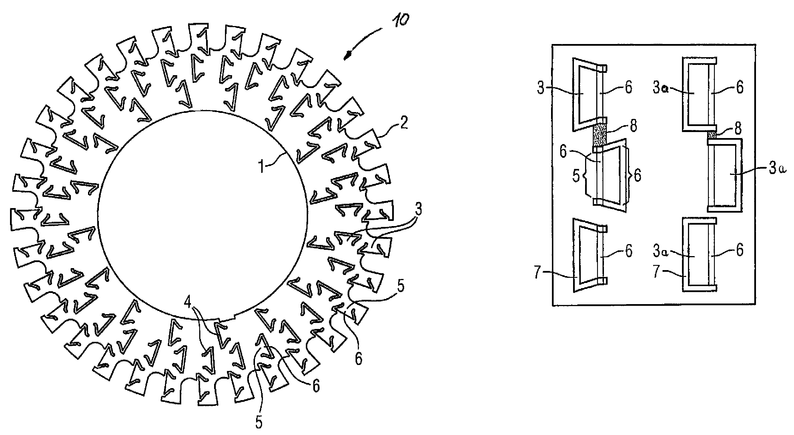
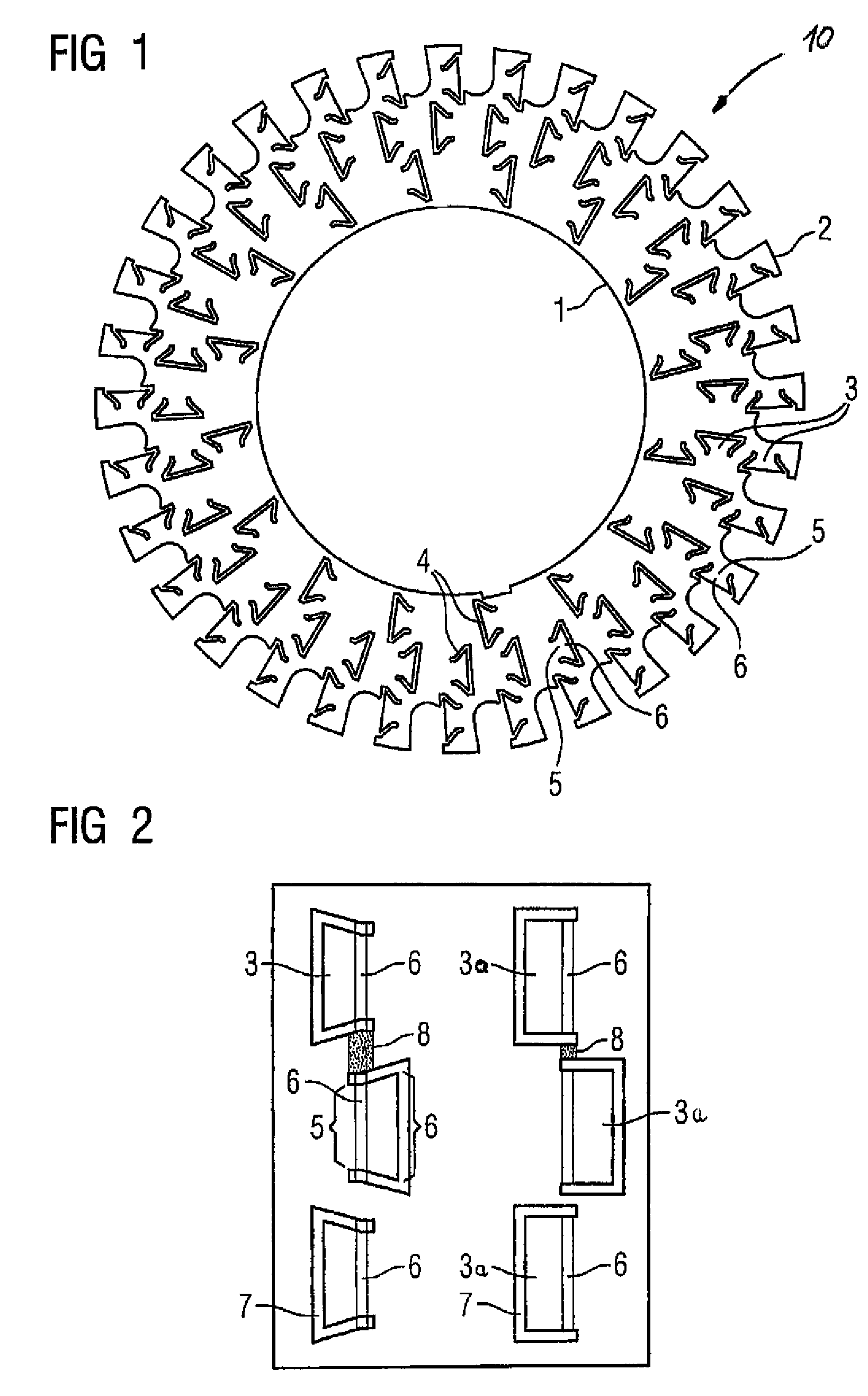
[0022]Turning now to the drawing, and in particular to FIG. 1, there is shown a schematic illustration of a lamination in accordance with the present invention for use in the construction of a stator core and / or rotor core of an electric machine or other devices such as motors, generators, transformers and the like. In the following description, reference is made to a rotor cor...


PUM

PropertyMeasurementUnit
angleaaaaaaaaaa
bending angleaaaaaaaaaa
lengthaaaaaaaaaa

Abstract

A lamination has at least one spacing strip which is formed by cutting out sheet-metal pieces from a metal sheet in order to define an inner boundary and an outer boundary of the lamination. A cut line is made in the metal sheet to define a contour for a spacing strip which is bent out of the main plane of the lamination.

Description

CROSS-REFERENCES TO RELATED APPLICATIONS[0001]This application is a continuation-in-part of prior filed copending PCT International application no. PCT / DE2004 / 002405, filed Oct. 28, 2004, which designated the United States and on which priority is claimed under 35 U.S.C. §120.BACKGROUND OF THE INVENTION[0002]The present invention relates, in general, to the field of electric machines, and more particularly to improvements in laminations for use in electric motors and / or other static or dynamic electric machines. The invention also relates to a method of making such laminations.[0003]Nothing in the following discussion of the state of the art is to be construed as an admission of prior art.[0004]In order to dissipate heat produced during operation of a motor, stacks of laminations, also called electrical steel sheets, are used, whereby laminations with spacing strips are arranged at defined intervals with respect to one another between laminations without spacing strips to thereby pr...

Claims


Application Information

Patent Timeline
Patent Type & Authority Patents(United States)
IPC IPC(8): H02K1/32
CPCH02K1/20Y10T29/49009
Inventor JESKE, RAINER
Owner SIEMENS AG
Why Eureka
Try Eureka