Method and device for identifying a damaged bearing of a rotating shaft

Inactive Publication Date: 2010-06-29
SIEMENS AG
View PDF11 Cites 5 Cited by
  • Summary
  • Abstract
  • Description
  • Claims
  • Application Information

AI Technical Summary

Benefits of technology

[0020]It has also proven to be advantageous if the limit value is monitored for exceedance in the range of a bearing pass frequency, since the absolute frequency response of the envelope rises particularly sharply in the range of a bearing pass frequency in the event of a damaged bearing.
[0021]It has also proven to be advantageous if a bearing pass frequency of the bearing is stored in a memory on a motor. This considerably simplifies the starting-up of the motor, since the motor can directly provide the bearing pass frequency to, for example, an open-loop and/or closed-loop control device for the open-loop and/or closed-loop control of the motor.

Problems solved by technology

Bearing damage often occurs wi

Method used


Image

  • Method and device for identifying a damaged bearing of a rotating shaft
  • Method and device for identifying a damaged bearing of a rotating shaft
  • Method and device for identifying a damaged bearing of a rotating shaft

Examples


Example

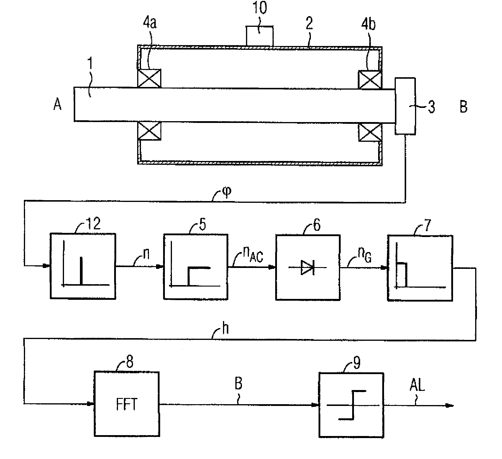
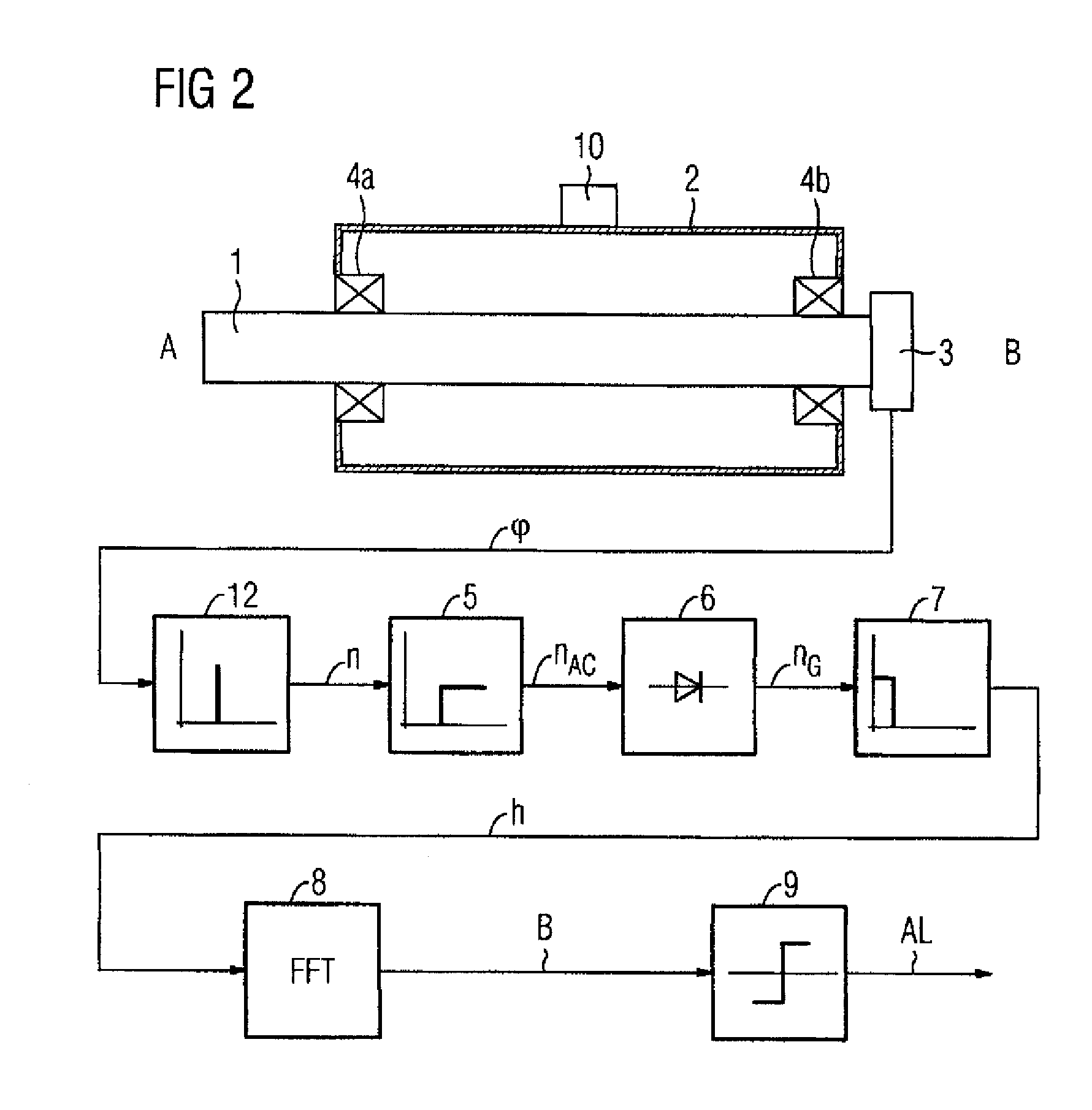
[0032]FIG. 2 illustrates the method according to the invention and the device according to the invention in the form of an exemplary embodiment. The motor illustrated in FIG. 2 substantially corresponds in terms of its basic design to the motor illustrated previously in FIG. 1. Identical elements in FIG. 2 are therefore provided with the same reference symbols as in FIG. 1. The essential difference with regard to the motor as per FIG. 1 is that the motor as per FIG. 2 does not have a vibration sensor 11 as per FIG. 1. According to the invention, the position signal of the position sensor 3, which position signal indicates the position φ of the motor shaft, is utilized to identify bearing damage of the B-side bearing 4b and / or of the A-side bearing 4a. The motor does of course comprise further elements, but these are not illustrated in FIG. 2 as they are not essential to the understanding of the invention.

[0033]The position φ is measured by the position sensor 3 and is supplied as an...


PUM


Abstract

The invention relates to a method and a device for identifying a damaged bearing (4a, 4b) of a rotating shaft (1). According to the invention: the rotational speed (n) of the shaft (1) is determined; the alternating component (nAC) of the rotational speed (n) is determined, together with a smooth curve (h) of said alternating component (nAC) of the rotational speed (n); the smooth curve (h) is converted into the frequency range and a frequency response (B) of the value of the smooth curve (h) is determined. Said frequency response (B) of the value of the curve is monitored for the passing of a threshold value (G1, G2, G3, G4) and if said threshold value (G1, G2, G3, G4) is exceeded, a damaged bearing (4a, 4b) is identified. The invention thus provides a method and a device for identifying a damaged bearing (4a, 4b) of a rotating shaft (1) of a motor, which do not require a vibration sensor (11) to identify a damaged bearing (4a, 4b) of said shaft (1).

Description

BACKGROUND OF THE INVENTION[0001]The invention relates to a method and to a device for identifying a damaged bearing of a rotating shaft.[0002]In motors, in particular in electric motors, the bearings of a rotating motor shaft of the motor must frequently be monitored for bearing damage.[0003]FIG. 1 illustrates a standard method and a standard device for identifying a damaged bearing of a rotating motor shaft of a motor. The motor as per FIG. 1 has two sides A and B, which are denoted in FIG. 1 by A and B. The motor comprises a motor shaft 1, which is mounted by means of two bearings 4a and 4b, and a housing 2. Rolling bearings, for example, can serve as bearings 4a and 4b. In order to measure the position, that is to say the angular position of the motor shaft in relation to an origin, and / or in order to measure the rotational speed of the motor shaft, the motor has a position sensor 3 which, in the example, is in the form of a resolver. The position sensor 3 outputs the position φ...

Claims


Application Information

Patent Timeline
IPC IPC(8): G01H1/00G01M99/00
CPCG01M13/045
Inventor FILBRY, KARL-HEINZ
Owner SIEMENS AG
Why Eureka
Try Eureka