Cornice fixture

Inactive Publication Date: 2010-06-29
HAFFAMIER KATHLEEN +1
View PDF39 Cites 11 Cited by
  • Summary
  • Abstract
  • Description
  • Claims
  • Application Information

AI Technical Summary

Problems solved by technology

Because the cornice board of a custom made fixture is normally made of wood, it must be cut to the desired size very accurately because it cannot expand.

Method used


Image

  • Cornice fixture
  • Cornice fixture
  • Cornice fixture

Examples


Embodiment Construction

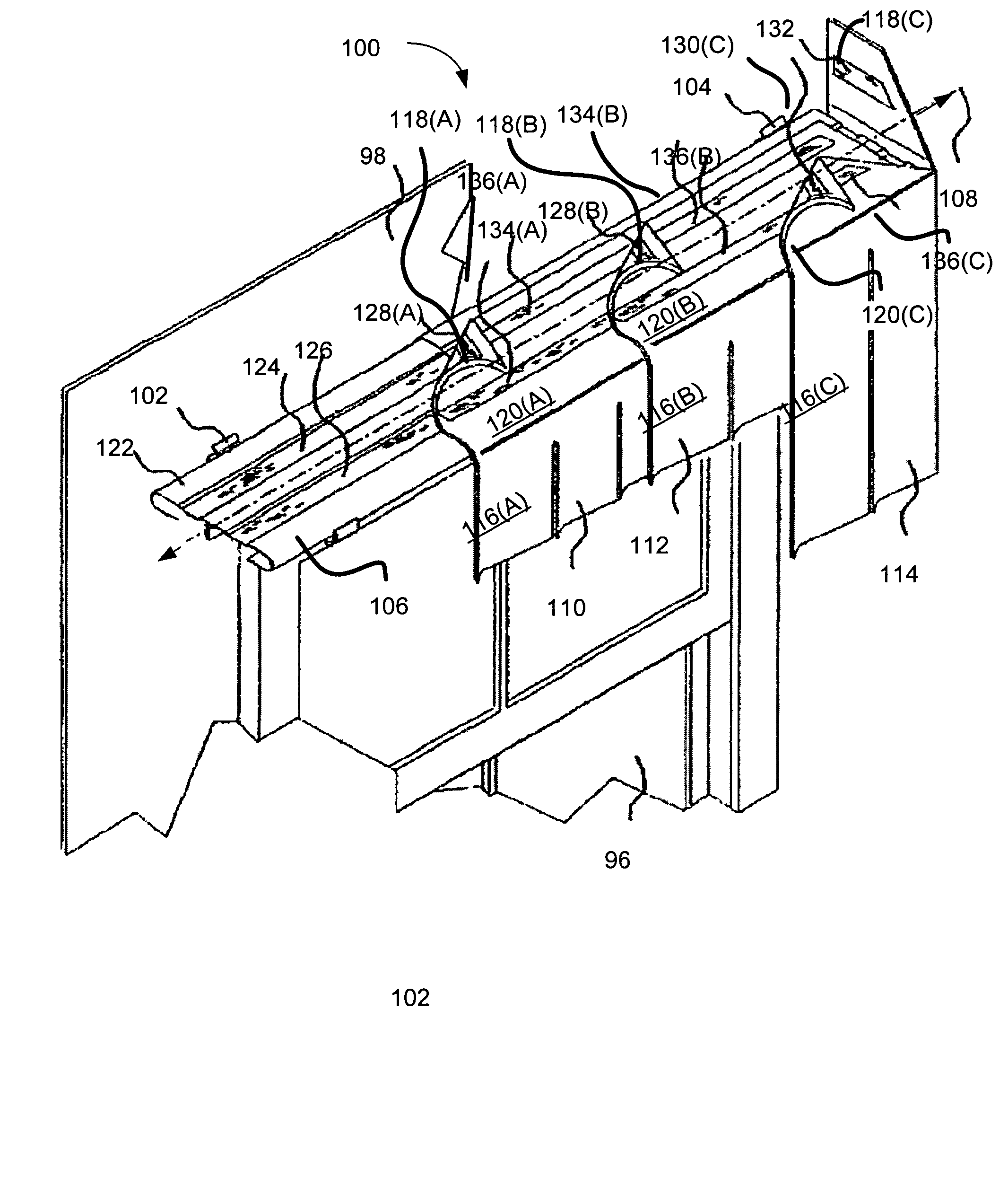
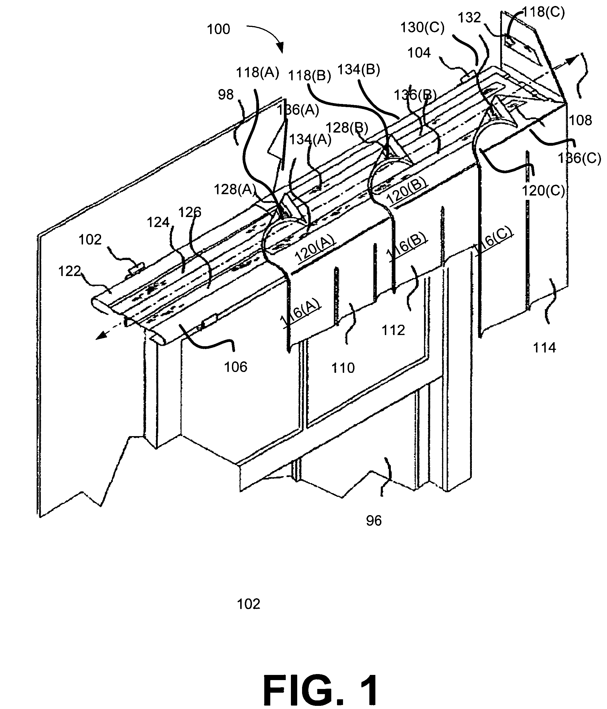
[0028]Referring to FIG. 1, a cornice fixture 100 is mounted to a wall 98 above a window 96. The cornice fixture 100 includes a pair of brackets 102 and 104 and a rod 106. The brackets 102 and 104 define a longitudinal axis denoted by the dashed line 108, and the rod 106 is slidably coupled to the brackets 102 and 104 such that the rod 106 can slide in directions that are generally parallel to the longitudinal axis 108.

[0029]It should be noted that the brackets 102 and 104 do not need to be centered around the window 96. Because the rod 106 extends past the brackets 102 and 104 and is adapted to slidably couple with the brackets 102 and 104, the rod 106 can be slid in the direction of the longitudinal axis 108 such that the rod 106 is centered around the window 96. With the rod 106 centered around the window 96 (or some other point), the cornice fixture 100 has the appearance of being centered around the window because most observers do not notice the brackets. Not needing to center ...


PUM


Abstract

A cornice fixture for decorating a wall and a method of installing the cornice fixture are disclosed. The cornice fixture includes a rod from which window treatments are hung and at least one bracket. Typically, the cornice fixture includes a pair of brackets, and the rod is slidably coupled to the brackets. Slidably coupling the rod to the brackets enables the installer to center the rod about a given point after the rod has been coupled to the bracket.

Description

CROSS-REFERENCE TO RELATED APPLICATION[0001]This application is a continuation in part of copending U.S. utility application entitled, “CORNICE FIXTURE,” having Ser. No. 10 / 907,510, filed Apr. 4, 2005, which is entirely incorporated herein by reference and which claimed priority to U.S. provisional application entitled, “SNAP FIT MODULAR CORNICE ROD SYSTEM,” having Ser. No. 60 / 592,962 filed Aug. 2, 2004, which is entirely incorporated herein by reference.TECHNICAL FIELD[0002]The present invention is generally related to hanging window treatments and, more particularly, is related to a system and method for slidably coupling a rod and a bracket.BACKGROUND OF THE INVENTION[0003]Many homes, especially well decorated homes, have decorative fixtures such as cornice fixtures, which can look like a three sided box. A cornice fixture is centered around a window and covers the top of the window. It is often made of wood, which is then padded and then covered in fabric. It can also be made of...

Claims


Application Information

Patent Timeline
Patent Type & Authority Patents(United States)
IPC IPC(8): A47H2/02
CPCA47H1/022A47H1/10A47H1/14E06B9/38A47H13/00A47H2/00A47H2201/02
Inventor HAFFAMIER, KATHLEENRINGER, ERIC MICHAEL
Owner HAFFAMIER KATHLEEN
Why Eureka
Try Eureka