Dimmable, high power factor ballast for gas discharge lamps

a technology of high power factor and ballast, which is applied in the direction of electric variable regulation, process and machine control, instruments, etc., can solve the problems of low input power factor, about 0.5 to 0.6, and achieve the effect of improving the dimming capability

Inactive Publication Date: 2010-07-06
SRIPATHY SAMPATH
View PDF16 Cites 29 Cited by
  • Summary
  • Abstract
  • Description
  • Claims
  • Application Information

AI Technical Summary

Benefits of technology

[0008]In preferred embodiments, the power factor correction circuit not only provides high input power factor, but also advantageously provides for improved dimming capability, specifically, dimming the discharge to low levels, while maintaining steady, non-flickering operation. Advantageously, a power factor correction circuit in accordance with preferred embodiments of the present invention is compatible with presently available phase cut dimmers used, for example, with incandescent lamps.

Problems solved by technology

Disadvantageously, this creates a highly distorted input current waveform that, in turn, causes the input power factor to be low, typically about 0.5 to 0.6.

Method used


Image

  • Dimmable, high power factor ballast for gas discharge lamps
  • Dimmable, high power factor ballast for gas discharge lamps
  • Dimmable, high power factor ballast for gas discharge lamps

Examples


Embodiment Construction

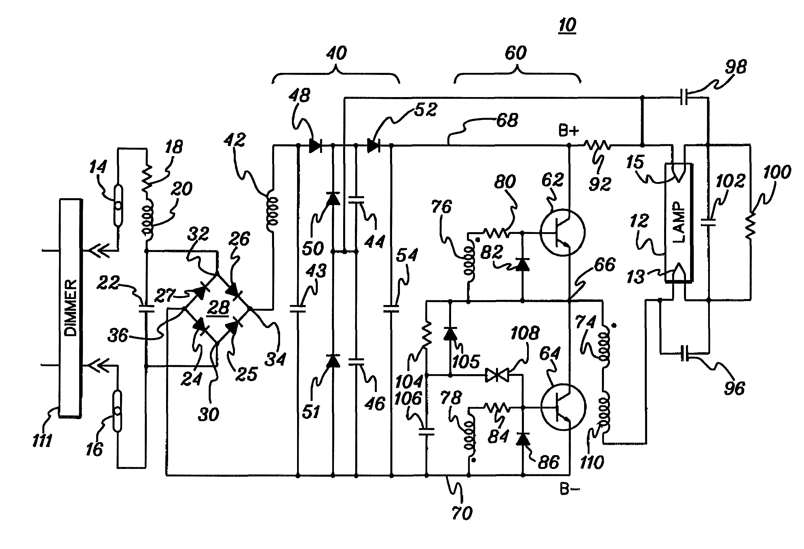
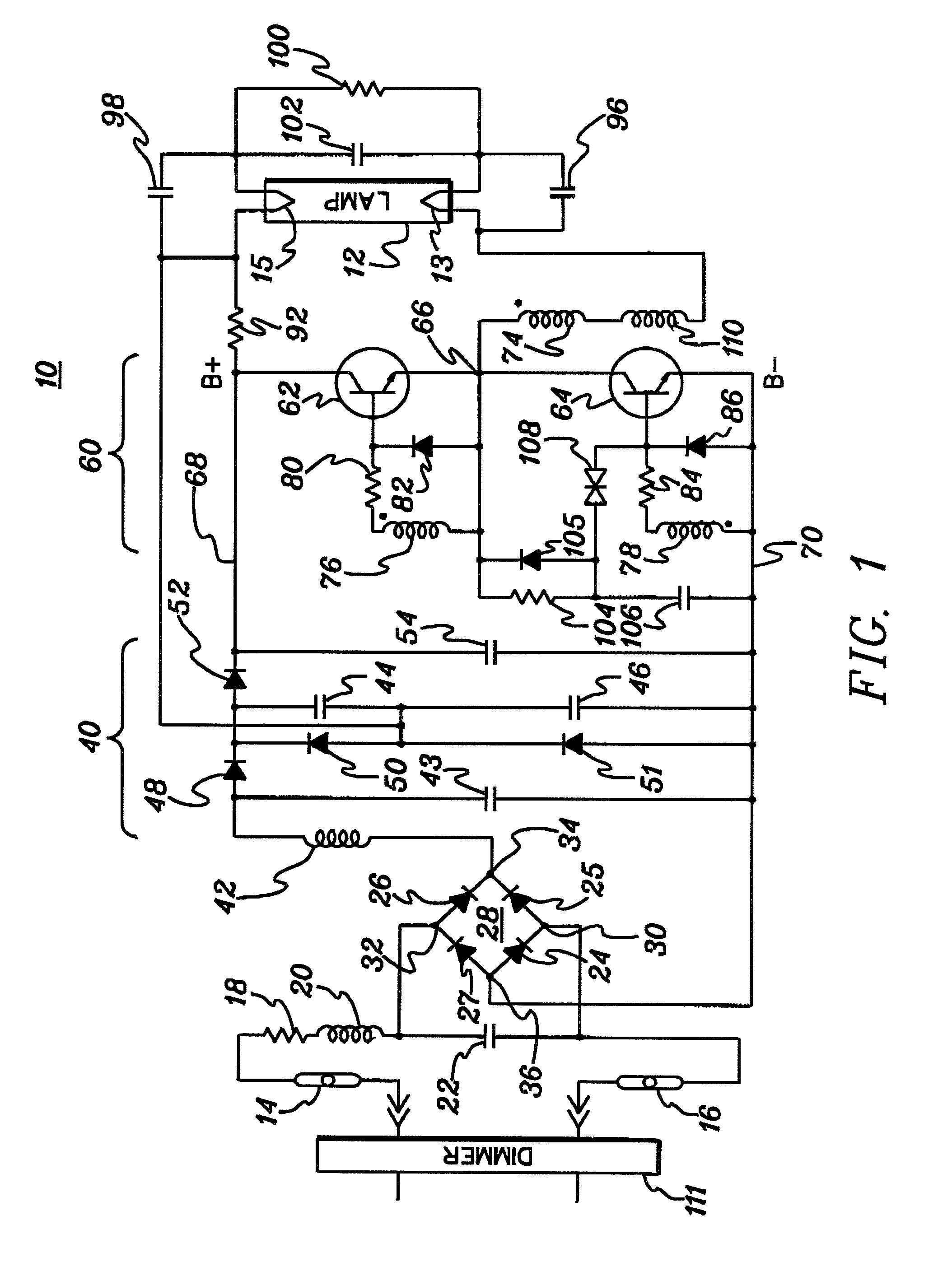
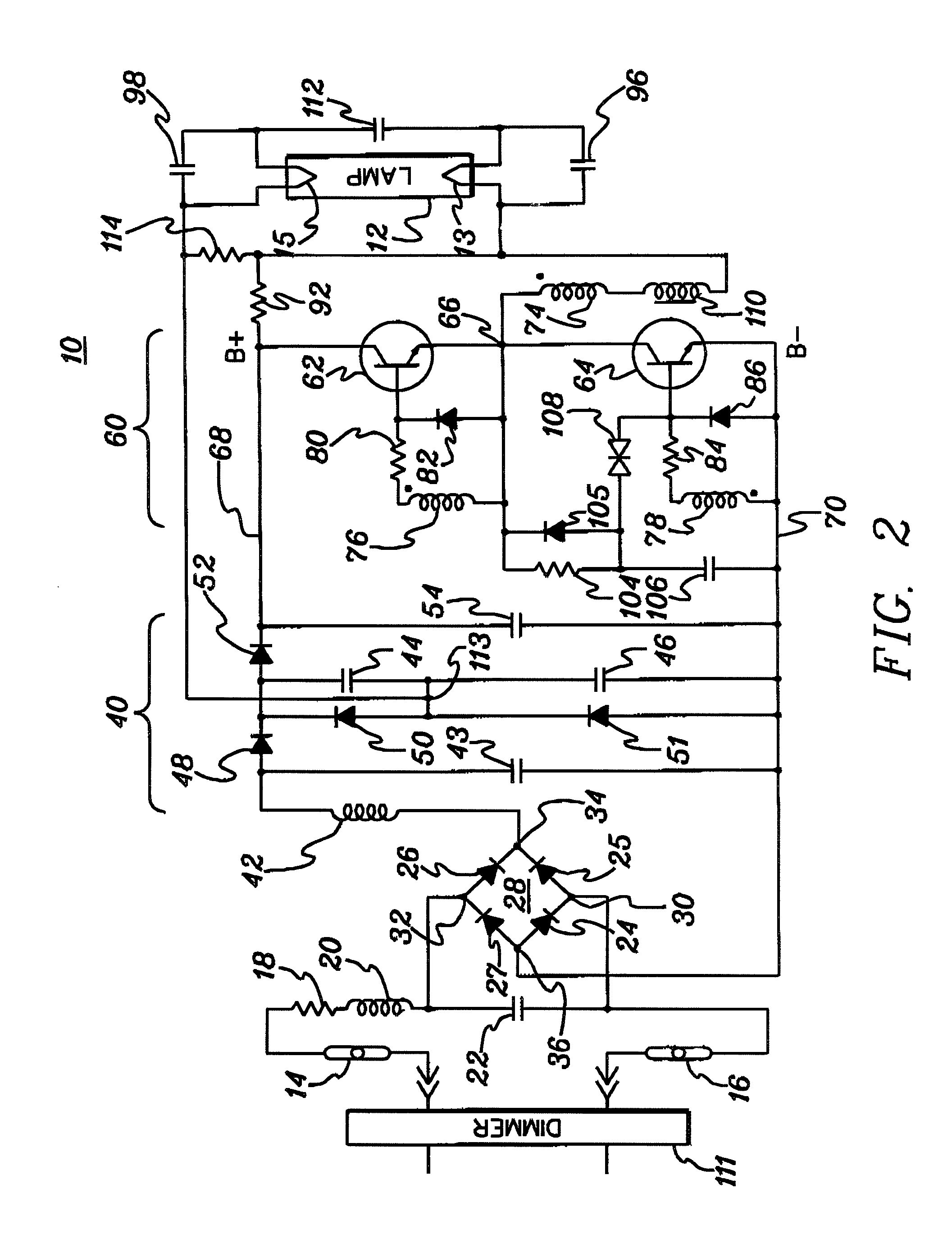
[0015]FIG. 1 schematically illustrates a dimmable, high power factor ballast 10 for operating a gas discharge lamp 12 in accordance with the present invention. Discharge lamp 12 may comprise, for example, a compact fluorescent lamp (CFL). Although embodiments of the present invention are described herein with respect to CFL's, it is to be understood that the principles of the present invention are not limited to ballasts for CFL's, but are applicable to other types of discharge lamps.

[0016]In the embodiment of FIG. 1, ballast 10 receives AC power at terminals 14 and 16; and a resistor 18 reduces inrush current when power is first applied to the ballast. In preferred embodiments, resistor 18 is a negative temperature coefficient (NTC) resistor that has one value at room temperature and a lower value after the resistor has been heated by the current flowing through it and by the heat dissipated by the other components in the ballast. Use of an NTC resistor is well known in the art as ...


PUM


Abstract

A ballast for operating a compact fluorescent lamp includes a power factor correction circuit and an energy storage capacitor coupled to the output thereof. The power factor correction circuit is configured to draw current from an AC power source during substantially more than half of the cycle of the input AC voltage waveform; i.e., when operated such that full power is supplied to the lamp. Energy transfer elements in the power factor correction circuit extract energy from the AC power source via an input rectifier, even when the peak voltage of the AC voltage waveform is substantially lower than the voltage of the energy storage capacitor, and transfer the energy to the energy storage capacitor a sufficient number of times during for each cycle of the input AC voltage waveform (e.g., at least 500 times for each full cycle of a 60 Hz input AC voltage waveform for a lamp operated at a frequency of 30 kHz), such that the energy storage capacitor remains substantially fully charged during steady-state ballast operation. The power factor circuit additionally provides for improved dimming capability, specifically, dimming the discharge to low levels, while maintaining steady, non-flickering operation.

Description

CROSS-REFERENCE TO RELATED APPLICATIONS[0001]This application claims priority to U.S. Provisional Application No. 60 / 849,952, entitled “DIMMABLE, HIGH POWER FACTOR BALLAST FOR GAS DISCHARGE LAMPS”, filed Oct. 6, 2006, which is hereby incorporated herein by reference in its entirety.FIELD OF THE INVENTION[0002]This invention relates generally to electronic ballasts for operating gas discharge lamps. More particularly, this invention relates to an electronic ballast with high input power factor and dimming capability for operating fluorescent lamps, including compact fluorescent lamps.BACKGROUND OF THE INVENTION[0003]Most compact fluorescent lamp ballasts draw current from the power line only during a relatively short time period near the peak of the input AC voltage waveform. Disadvantageously, this creates a highly distorted input current waveform that, in turn, causes the input power factor to be low, typically about 0.5 to 0.6. Another area for improvement in compact fluorescent l...

Claims


Application Information

Patent Timeline
Patent Type & Authority Patents(United States)
IPC IPC(8): H05B37/00H05B37/02
CPCH05B41/282H05B41/2986H05B41/392Y02B20/183Y02B20/19Y02B20/00
Inventor LU, NINGLIU, JUNASHOKKUMAR, VENUGOPAL
Owner SRIPATHY SAMPATH
Why Eureka
Try Eureka