Personal watercraft

Active Publication Date: 2011-10-13
KAWASAKI MOTORS LTD
View PDF3 Cites 0 Cited by
  • Summary
  • Abstract
  • Description
  • Claims
  • Application Information

AI Technical Summary

Benefits of technology

[0007]In accordance with such a configuration, since at least a portion of the pressure receiving section of the resistive element in the operating position is located outward relative to the coupling portion where the resistive element is coupled to the body, in the width direction of the body, the force applied to the body has a substantially horizontal major component in a princ

Problems solved by technology

If the body of the watercraft is designed to increase the water resistance a

Method used


Image

  • Personal watercraft
  • Personal watercraft
  • Personal watercraft

Examples


Example

[0017]Hereinafter, an embodiment of the present invention will be described with reference to the drawings. As used herein, the stated directions refer to directions from the perspective of a rider straddling a watercraft, unless otherwise explicitly noted.

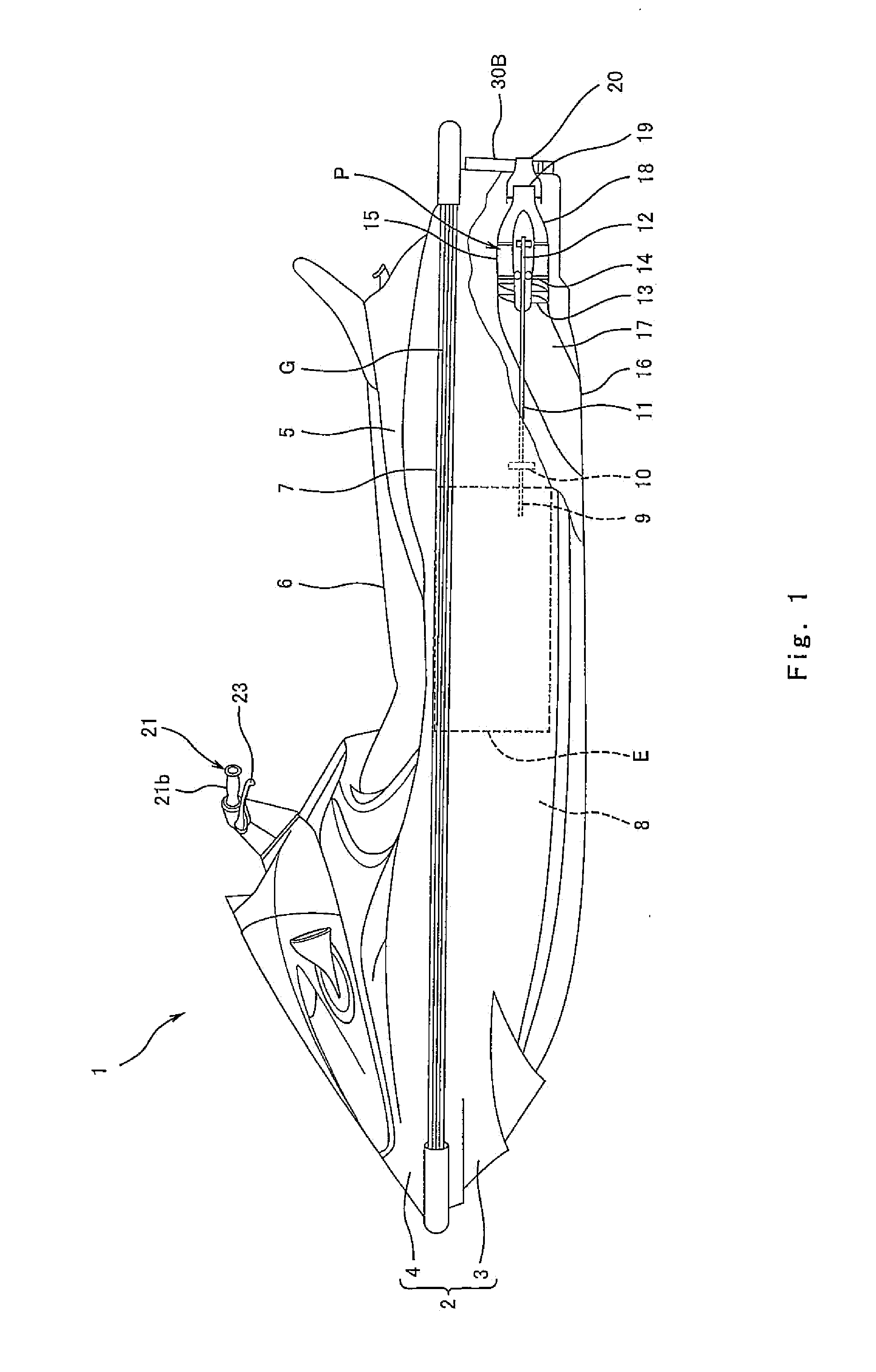
[0018]FIG. 1 is a left side view of personal watercraft 1 according to an embodiment of the present invention. As shown in FIG. 1, the watercraft 1 includes a body 2 including a hull 3 and a deck 4 covering the hull 3 from above. The hull 3 and the deck 4 are connected to each other by a gunnel line section G which protrudes horizontally outward from the body 2. A center region in a width direction of the rear portion of the deck 4 protrudes upward to form a protruding portion 5. A seat 6 is mounted over the upper surface of the protruding portion 5. A deck floor 7 is provided on opposite (right and left) sides in the width direction of the protruding portion 5. The deck floor 7 is lower than the protruding portion 5 and is substa...


PUM


Abstract

A personal watercraft configured to eject water rearward from a body thereof to generate a propulsive force, includes a pair of right and left resistive elements which are attached to the body and configured to be able to receive water resistance during travel of the watercraft. The resistive elements are configured to move between an operating position and a non-operating position, the water resistance being larger in the operating position than in the non-operating position. Each of the resistive elements includes a pressure receiving section configured to receive the water resistance in the operating position, and wherein in the operating position, at least a portion of the pressure receiving section is located outward relative to a coupling portion where the resistive element is coupled to the body, in a width direction of the body.

Description

BACKGROUND OF THE INVENTION[0001]1. Field of the Invention[0002]The present invention relates to a personal watercraft (PWC) which is configured to eject water rearward from a body thereof to generate a propulsive force.[0003]2. Description of the Related Art[0004]A personal watercraft is configured to be decelerated by water resistance applied to a body thereof. It is desired that the personal watercraft be decelerated with a high responsiveness to a rider's operation of moving a throttle lever to a closed position. If the body of the watercraft is designed to increase the water resistance applied to the body, its acceleration capability and fuel efficiency decrease.[0005]U.S. Pat. No. 6,691,634 and U.S. Pat. No. 7,007,621 disclose a technique in which a resistive element protrudes downward from a hull bottom as desired at the rear portion of a body to allow the body to be decelerated by the water resistance. If the water resistance applied to the resistive element protruding downw...

Claims


Application Information

Patent Timeline
IPC IPC(8): B63H25/44
CPCB63B35/731B63H25/44B63B39/061B63B34/10
Inventor KAMIO, KUNIHIKO
Owner KAWASAKI MOTORS LTD
Why Eureka
Try Eureka