

Adapter optical system and image pickup apparatus including the same
- Summary
- Abstract
- Description
- Claims
- Application Information
AI Technical Summary
Benefits of technology
Problems solved by technology
Method used
Image

Examples
embodiment 1
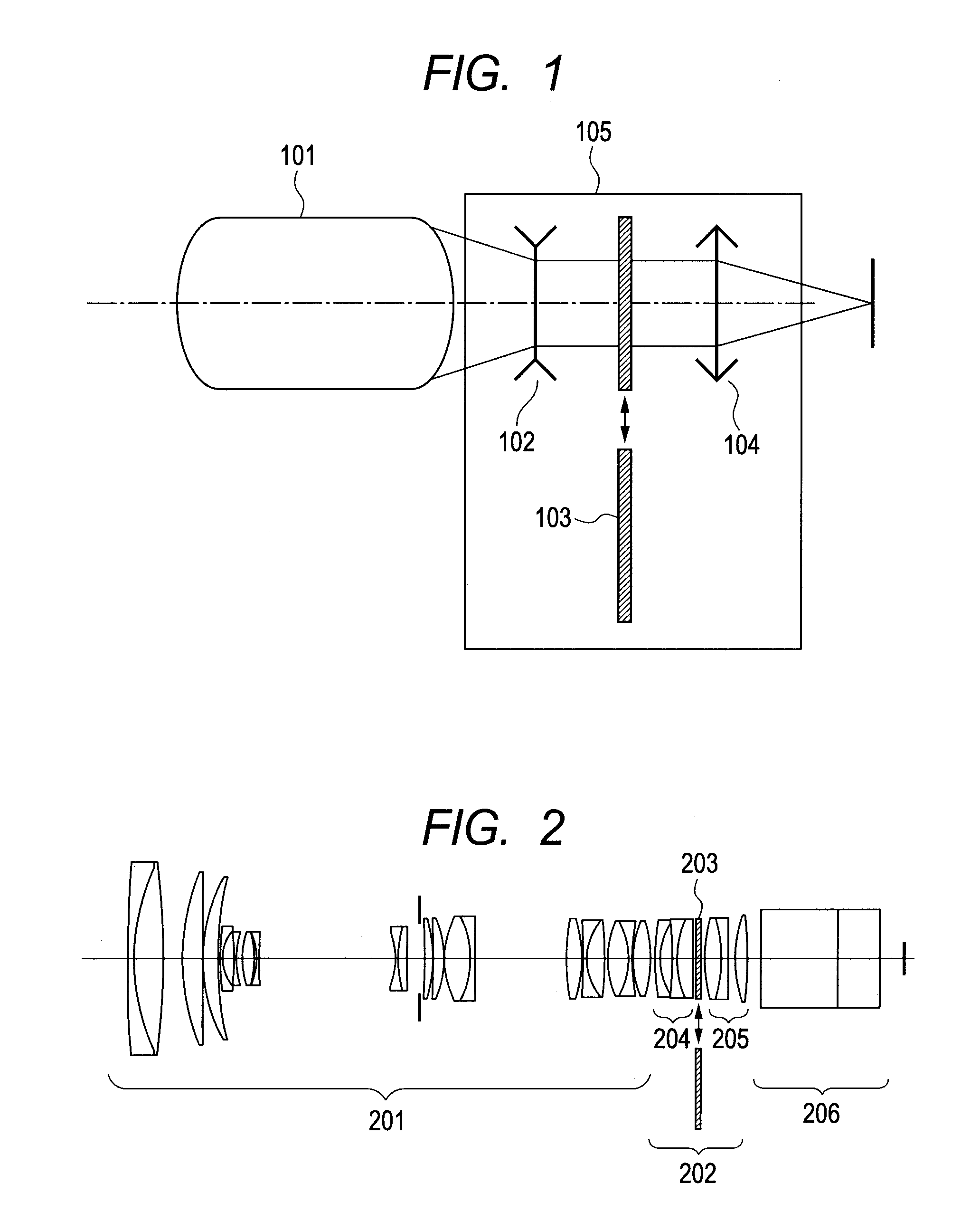
[0039]FIG. 2 is an optical cross sectional view of an image pickup optical system including an adapter optical system of Embodiment 1 of the present invention. A detachable adapter optical system 202 is attached between a zoom lens 201 as the image pickup lens and a camera optical system 206 in the optical path. The adapter optical system 202 includes, in order from the object side, a first optical unit 204 having negative refractive power, an optical element (second optical unit) 203 that can be inserted in and removed from the optical path, and a third optical unit 205 having positive refractive power. The first optical unit 204 has a first cemented lens constituted by a positive lens and a negative lens, and a camera-body-side surface of the negative lens of the first cemented lens is a concave surface. The third optical unit 205 has a second cemented lens constituted by a positive lens and a negative lens, an image-pickup-lens-side surface of the negative lens of the second ceme...
embodiment 2
[0042]FIG. 5 is an optical cross sectional view of an image pickup optical system including an adapter optical system of Embodiment 2 of the present invention. This embodiment has a similar structure to that of Embodiment 1. The incident inclination angle (incident converted inclination angle) of the axial beam entering an optical element (second optical unit) 503 is −0.23, and further a curvature is given so that positive refractive power is given to an object side surface 507 of the optical element 503. FIG. 6A is a longitudinal aberration diagram at a wide angle end when focusing at infinity in a state in which an adapter optical system 502 is attached to a zoom lens 501 as the image pickup lens, and the optical element 503 is inserted in the optical path. FIG. 6B is a longitudinal aberration diagram at the wide angle end when focusing at infinity in a state in which the adapter optical system 502 is attached to the zoom lens 501, and the optical element 503 is removed from the o...
numerical embodiment 1
[0046]
Unit: mmSurface dataSurfaceEffectiveNumberrdndνddiameter 1600.2612.201.7552027.572.83 281.46111.421.4970081.669.52 3−290.9567.6369.08 486.7017.861.6204160.365.46 53044.7100.1564.99 666.0166.011.7291654.761.52 7145.708(Variable)60.42 8111.4450.801.8830040.823.69 916.8124.6520.0310−47.8420.701.8160046.619.801133.7792.2419.271228.9445.201.8051825.419.7213−29.1920.5419.3114−24.6640.701.7880047.418.9315132.572(Variable)18.4516−28.8060.751.7432049.320.251737.2183.811.8466623.922.2418449.023(Variable)23.1319 (Stop)∞1.8027.2020−231.2333.331.6700347.228.3321−49.1330.2029.1422−170.3654.051.5174252.429.9423−38.6250.2030.512436.31510.161.4874970.231.2725−35.5641.661.8340037.230.5226∞36.0030.512797.3856.351.5013756.430.3228−44.4380.2030.0429−535.6531.401.8340037.228.543021.0167.221.5013756.426.7631−424.0931.5026.793238.5058.291.5182358.926.7533−27.4821.401.7725049.626.503491.3600.3026.933538.4296.841.5317248.827.6336−52.4072.0027.55(At time of attaching adapter opticalelement: at time of i...
PUM
 Abstract
Description
Claims
Application Information