microscope

Inactive Publication Date: 2013-07-04
CANON KK
View PDF9 Cites 0 Cited by
  • Summary
  • Abstract
  • Description
  • Claims
  • Application Information

AI Technical Summary

Benefits of technology

[0010]According to an aspect of the present invention, there is provided a microscope including an illumination system that illuminates a specimen, a stage on which the specimen is to be placed, and an objective lens that forms an image of the specimen illuminated by the illumination system. The stage includes a fixed member whose position and inclination with respect to the objective lens are fixed, a specimen holding member at least one of whose position and inclination with respect to the fixed member is changeable, and a supporting member that supports the specimen holding member with respect to the fixed member. A connection between the supporting member and

Problems solved by technology

Furthermore, such image data needs to be quickly acquirable.
This enables quick acquisition of image data but makes it difficult to acquire an image that is in focus at every point of the area defined by that angle of view.
There

Method used


Image

  • microscope
  • microscope
  • microscope

Examples


Example

First Exemplary Embodiment

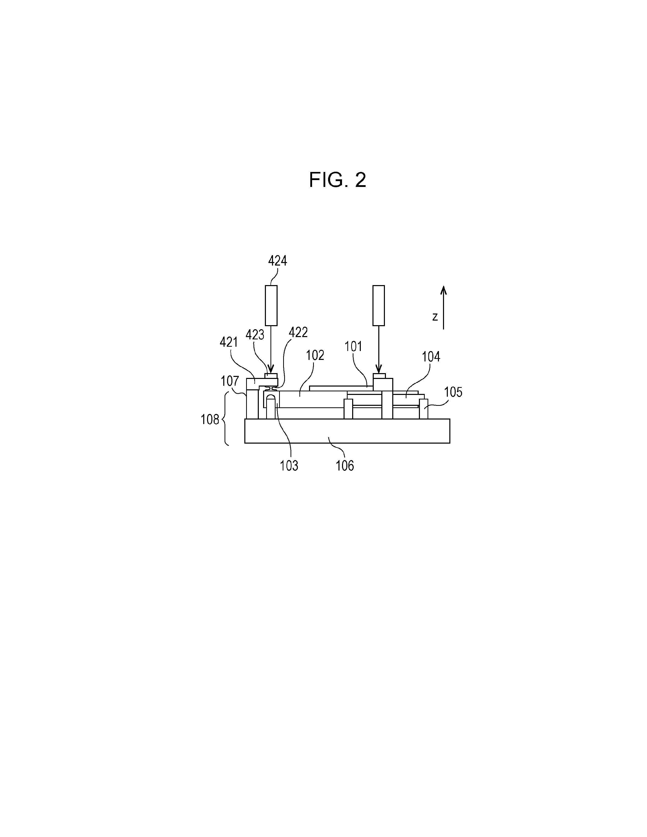
[0028]FIG. 2 is a side view of the specimen moving stage 108. FIG. 3 is a top view of the specimen moving stage 108.

[0029]Referring to FIGS. 2 and 3, the preparation 101 is placed on a specimen holding member 102. The specimen holding member 102 is connected to supporting members 104 via connecting members 103 included in the specimen holding member 102. The supporting members 104 are connected to projections 105 included in a specimen-moving-stage base (hereinafter simply referred to as base) 106. The projections 105 may be integral portions of the base 106. The projections 105 and the base 106 may be formed together in a mold. Actuators 107 are provided on the base 106.

[0030]The base 106 is a fixed member whose position and inclination with respect to the objective lens 303 are fixed. At least one of the position and the inclination of the specimen holding member 102 with respect to the base 106 and thus with respect to the objective lens 303 is changeabl...

Example

Second Exemplary Embodiment

[0039]FIG. 4 is a side view of a specimen moving stage 108 according to a second exemplary embodiment of the present invention.

[0040]In the second exemplary embodiment, a buffer mechanism including an elastic hinge 532 is provided between each connecting member 103 and the specimen holding member 102. A target 533 is provided directly on each actuator 107. The position of the target 533 is measured with the laser displacement sensor 424 provided above the target 533.

[0041]In the second exemplary embodiment also, the target 533 does not incline because of the presence of the buffer mechanism including the elastic hinge 532 even if the specimen holding member 102 is driven by the actuator 107 in such a manner as to incline. Therefore, the position of the target 533 is measured accurately, and the driving by the actuator 107 is controlled with high accuracy on the basis of the measurement.

Example

Third Exemplary Embodiment

[0042]FIG. 5 is a side view of a specimen moving stage 108 according to a third exemplary embodiment of the present invention.

[0043]In the third exemplary embodiment, another buffer mechanism including an elastic hinge 641 is added to the configuration according to the second exemplary embodiment. The elastic hinge 641 is provided between each supporting member 104 and a corresponding one of the projections 105. The elastic hinge 641 according to the third exemplary embodiment does not tend to rotate about the longitudinal axis of the supporting member 104.

[0044]The presence of the elastic hinge 641 suppresses the rotation of the connecting member 103 due to the disagreement between the point on which the actuator 107 acts and the center of the supporting member 104. Therefore, the position of the target 533 is measured more accurately, and the driving by the actuator 107 is controlled with higher accuracy on the basis of the measurement.

Modifications

[0045]...


PUM


Abstract

A microscope includes an illumination system, a stage, and an objective lens that forms an image of a specimen. The stage includes a fixed member whose position and inclination are fixed, a specimen holding member at least one of whose position and inclination is changeable, and a supporting member that supports the specimen holding member. A connection between the supporting member and the specimen holding member and a connection between the supporting member and the fixed member reside near sides of the specimen holding member. The microscope further includes an actuator that changes at least one of the position and the inclination of the specimen holding member with respect to the fixed member, and a buffer mechanism that suppresses transmission of any changes in the inclination of the specimen holding member to the actuator. The actuator and the specimen holding member are connected with the buffer mechanism interposed therebetween.

Description

BACKGROUND OF THE INVENTION[0001]1. Field of the Invention[0002]The present invention relates to a microscope used in observing an image of a specimen.[0003]2. Description of the Related Art[0004]It is known that doctors often diagnose diseases on the basis of image data on specimens (samples such as cells or tissues of the body) that is acquired through digital microscopes. Doctors are required to make diagnoses correctly and quickly. Hence, image data to be acquired through digital microscopes needs to be easy to make diagnoses. Furthermore, such image data needs to be quickly acquirable.[0005]When the angle of view of a microscope defined by an objective lens is increased, the area of an image to be acquired at a time increases. This enables quick acquisition of image data but makes it difficult to acquire an image that is in focus at every point of the area defined by that angle of view. This is because each specimen is not flat and has undulations. Hence, the focal plane (a pla...

Claims


Application Information

Patent Timeline
IPC IPC(8): G02B21/26
CPCG02B21/26
Inventor FUJII, HIROFUMIYANAGISAWA, MICHIO
Owner CANON KK
Why Eureka
Try Eureka