Gas sensor

Pending Publication Date: 2022-01-13
NGK INSULATORS LTD
View PDF0 Cites 0 Cited by
  • Summary
  • Abstract
  • Description
  • Claims
  • Application Information

AI Technical Summary

Benefits of technology

[0011]In this case, the measurement pump cell may pump out the oxygen by applying a measurement pump current serving as the repeatedly on-off controlled pump current between the inner measurement electrode and the outer measurement electrode. In other words, among the main pump cell, the auxiliary pump cell, and the measurement pump cell, at least the measurement pump cell may be caused to operate by using an intermittent pump current. Accordingly, a change in the catalytic activity of the inner measurement electrode due to use of the gas sensor can be suppressed. A change in the catalytic activity of the inner measurement electrode has a greater effect on the sensitivity for detecting the specific gas concentration in the gas sensor than a change in the catalytic activity of the inner main pump electrode and the inner auxiliary pump electrode. Therefore, deterioration in the detection sensitivity may be readily minimized by suppressing a change in the catalytic activity of the inner measurement electrode.
[0012]In this case, the gas sensor according to the present invention may further include a reference electrode, a measurement-voltage detection device, a measurement-pump-cell control device, and a specific-gas-concentration detection device. The reference electrode is disposed inside the element body and receives a reference gas serving as a reference for detection of the specific gas concentration. The measurement-voltage detection device detects a measurement voltage between the reference electrode and the inner measurement electrode. The measurement-pump-cell control device controls the measurement pump current based on the measurement voltage during a second period so as to set an oxygen concentration in the measurement chamber to a predetermined low concentration. The second period is one of a first period in which a change has occurred in the measurement voltage due to the measurement pump current being in an on mode and a second period in which the change in the measurement voltage has receded as compared with the first period due to the measurement pump current being in an off mode. The specific-gas-concentration detection device detects the specific gas concentration

Problems solved by technology

A change in the catalytic activity may sometimes lead to a problem in the gas sensor,

Method used


Image

  • Gas sensor
  • Gas sensor
  • Gas sensor

Examples


Example

Practical Example 1

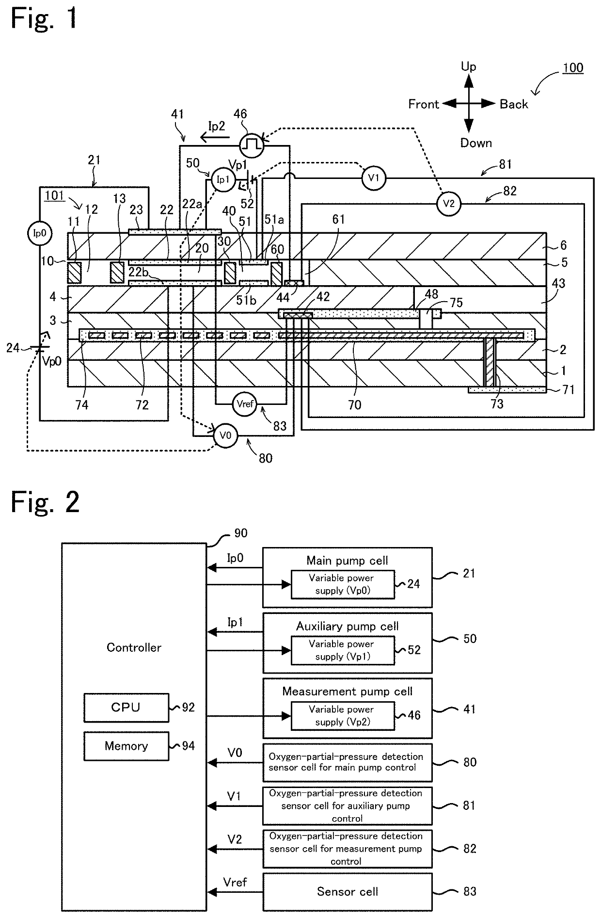
[0106]Practical Example 1 is achieved by fabricating the gas sensor 100 shown in FIGS. 1 and 2. The sensor element 101 is fabricated as follows. First, ceramic green sheets corresponding to the individual layers 1 to 6 are each formed by mixing zirconia particles having 4 mol % of yttria added thereto as a stabilizer with an organic binder, a dispersant, a plasticizer, and an organic solvent, and then molding the mixture by tape molding. Then, the ceramic green sheets corresponding to the individual layers undergo hole-drilling, where appropriate, and screen-printing of a pattern of a conductive paste for forming electrodes and a circuit, and are subsequently stacked and pressure-bonded, so that a pressure-bonded body is obtained. A pattern for the measurement electrode 44 is formed by screen-printing a conductive paste having a mixture of zirconia particles and an organic binder onto Pt and Rh serving as noble metals. Then, an unbaked layered body having the size...

Example

Practical Example 2

[0107]In Practical Example 2, a gas sensor 100 similar to that in Practical Example 1 is fabricated except that the pump current Ip2 to be applied by the pulse power source 46 is changed. The pump current Ip2 to be applied by the pulse power source 46 is a burst pulse current shown in FIG. 6, has a frequency of 100 Hz (i.e. a cycle T of 0.1 s), has five pulses per cycle, and has 50% as the proportion (i.e., duty ratio) of the oscillation period TA occupying the cycle T (burst cycle).

Example

Practical Example 3

[0108]In Practical Example 3, a gas sensor 100 similar to that in Practical Example 1 is fabricated except that the frequency is set to 200 Hz (i.e., the cycle T is set to 0.05 s).


PUM


Abstract

A gas sensor detects a specific gas concentration in a measurement-object gas and includes an element body and one or more pump cells. The element body includes an oxygen-ion-conductive solid electrolyte layer and is provided with a measurement-object gas flow section therein. The measurement-object gas flow section receives a measurement-object gas and allows the measurement-object gas to flow therethrough. The one or more pump cells each have an inner electrode and an outer pump electrode and pump out oxygen from around the inner electrode to around the outer pump electrode. The inner electrode is disposed in the measurement-object gas flow section and contains a catalytically-active noble metal. At least one pump cell of the one or more pump cells pumps out the oxygen by applying a repeatedly on-off controlled pump current between a measurement electrode and the outer pump electrode.

Description

CROSS-REFERENCE TO RELATED APPLICATION[0001]This application is a continuation application of PCT / JP2020 / 013415, filed on Mar. 25, 2020, which claims the benefit of priority of Japanese Patent Application No. 2019-064322, filed on Mar. 28, 2019, the entire contents of which are incorporated herein by reference.BACKGROUND OF THE INVENTION1. Field of the Invention[0002]The present invention relates to gas sensors.2. Description of the Related Art[0003]A known gas sensor in the related art detects the concentration of a specific gas, such as NOx, in a measurement-object gas, such as exhaust gas of an automobile. For example, Patent Literature 1 describes a gas sensor including a layered body of a plurality of oxygen-ion-conductive solid electrolyte layers, a main pump cell, and a measurement pump cell. The main pump cell includes an inner pump electrode disposed in a measurement-object gas flow section inside the layered body, and also includes an outer pump electrode disposed outside ...

Claims


Application Information

Patent Timeline
IPC IPC(8): G01N27/41G01N33/00G01N27/407G01N27/30
CPCG01N27/41G01N33/0037G01N27/301G01N27/4075G01N27/4071G01N27/419Y02A50/20
Inventor SEKIYA, TAKAYUKIWATANABE, YUSUKE
Owner NGK INSULATORS LTD
Why Eureka
Try Eureka