
Driving force control apparatus

Active Publication Date: 2020-02-13
HONDA MOTOR CO LTD
View PDF0 Cites 0 Cited by
  • Summary
  • Abstract
  • Description
  • Claims
  • Application Information

AI Technical Summary

Benefits of technology

The present invention is a driving force control system for vehicles that can detect the posture of an occupant and the acceleration of the vehicle, and adjust the driving force distribution between the front and rear wheels or the left and right wheels to suppress any changes in the driver's posture. This system uses an electronic control unit with a microprocessor and memory to calculate the required driving force and make the necessary adjustments to the driving force distribution. The technical effect of this invention is to provide a safer driving experience for the driver and to enhance the overall stability and efficiency of the vehicle.

Problems solved by technology

In the apparatus taught by JP2007-153160A, however, the expedient of applying vehicle driving force control to keep perceived acceleration within a comfortable range is apt to result in vehicle actual driving force diverging greatly from required driving force.

Method used


Image

  • Driving force control apparatus
  • Driving force control apparatus
  • Driving force control apparatus

Examples


Embodiment Construction

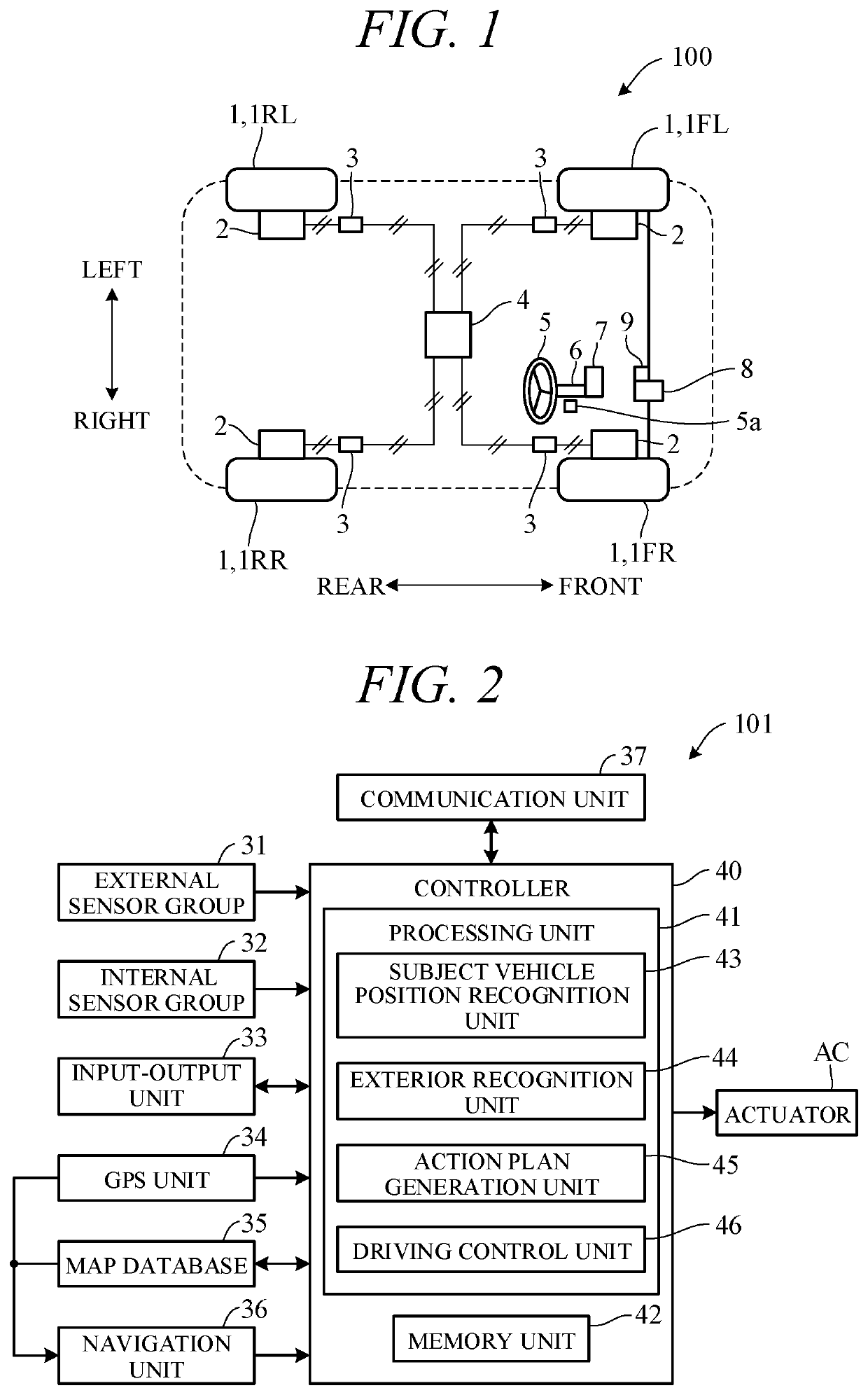
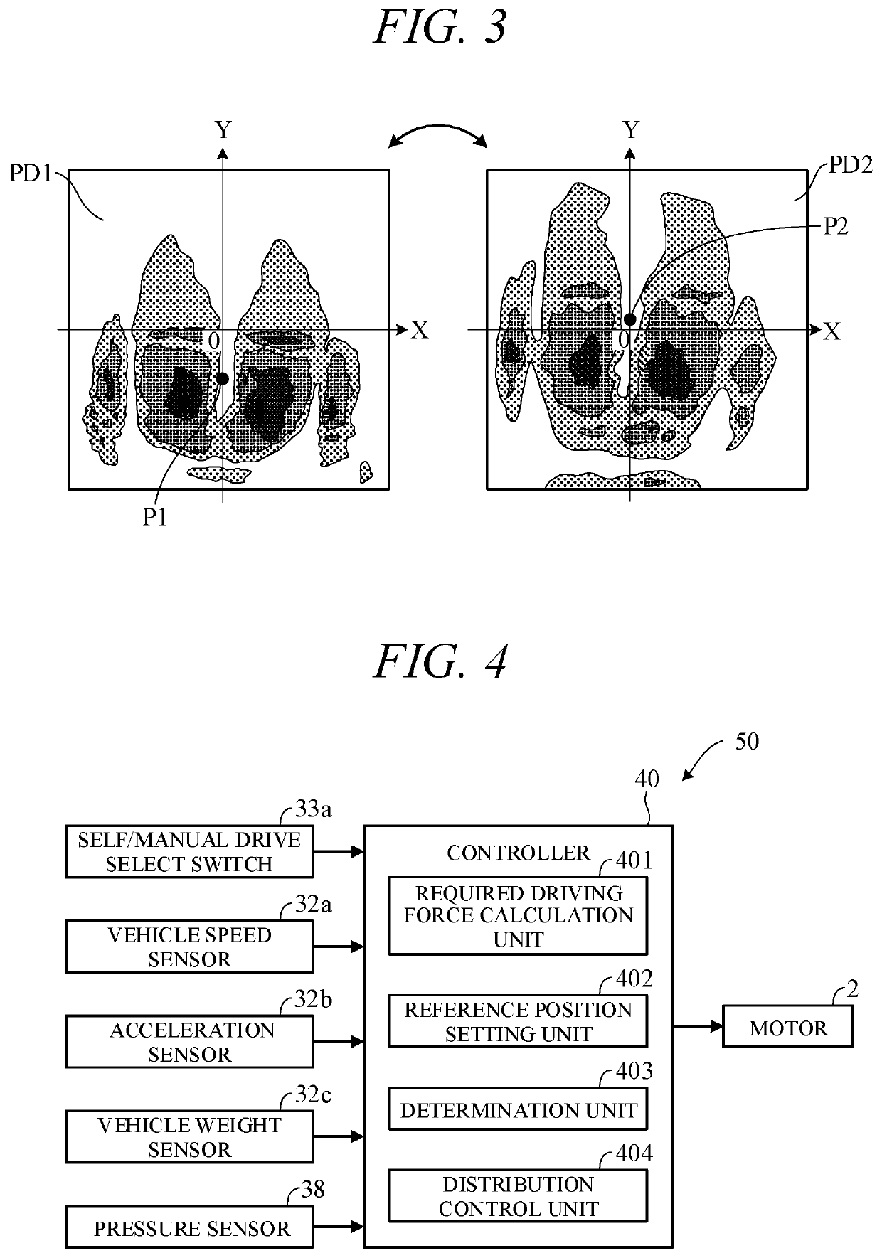
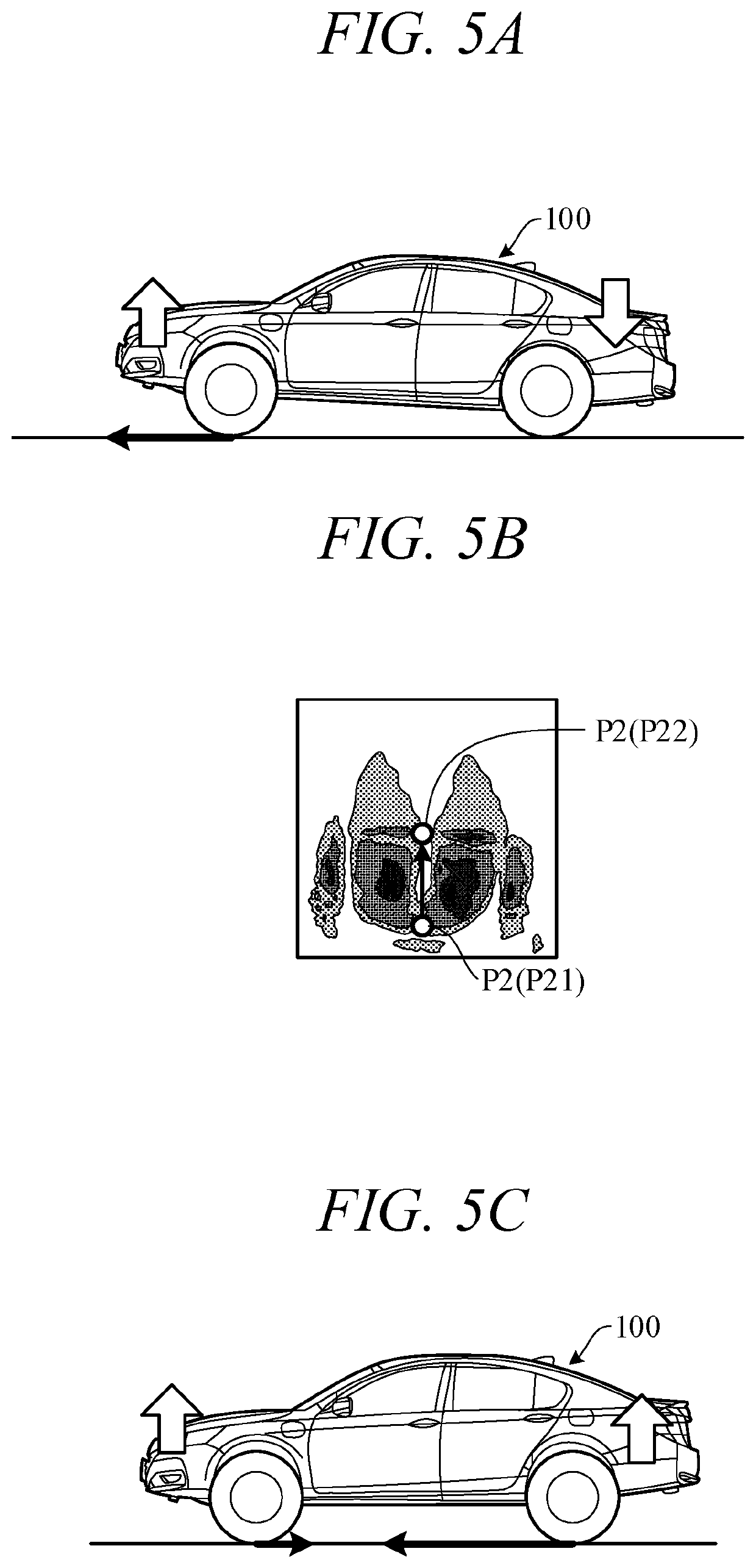
[0019]Hereinafter, an embodiment of the present invention is explained with reference to FIGS. 1 to 8. First, configurations of a vehicle (also called “subject vehicle”) to which the present embodiment is applied are explained. FIG. 1 is a diagram showing a configuration overview of a driving system of a vehicle 100 incorporating a driving force control apparatus according to an embodiment of the present invention. The vehicle 100 is a vehicle with a self-driving capability, i.e., self-driving vehicle. The vehicle 100 is not limited to driving in a self-drive mode requiring no driver driving operations but is also capable of driving in a manual drive mode by driver operations.

[0020]As shown in FIG. 1, the vehicle 100 is a four-wheel-drive vehicle whose four wheels 1 on front left and right, and rear left and right, namely, left and right front wheels 1FL, 1FR, and left and right rear wheels 1RL, 1RR, are all drive wheels. A motor (electric motor) 2 is connected to each of the drive ...


PUM


Abstract

A driving force control apparatus including a posture detecting part detecting a riding posture of an occupant; an acceleration detecting part detecting an acceleration of a vehicle; a driving force generation part generating a driving force in a manner enabling to change a driving force distribution between a front and rear wheels or between a left and right wheels; and a microprocessor. The microprocessor is configured to perform calculating a required driving force, and controlling the driving force generation part so as to change the driving force distribution to a target driving force distribution to suppress a change of the riding posture while generating the required driving force when a magnitude of the acceleration is greater than or equal to a predetermined magnitude and a degree of change of the riding posture is greater than or equal to a predetermined degree.

Description

CROSS-REFERENCE TO RELATED APPLICATION[0001]This application is based upon and claims the benefit of priority from Japanese Patent Application No. 2018-150657 filed on Aug. 9, 2018, the content of which is incorporated herein by reference.BACKGROUND OF THE INVENTIONField of the Invention[0002]This invention relates to a driving force control apparatus configured to control driving force of a vehicle.Description of the Related Art[0003]Conventionally, there is a known apparatus that uses load sensors provided in a seat cushion and a seat back to detect change in load acting on the seat cushion and change in load acting on the seat back and that controls vehicle driving force so as to keep occupant-perceived acceleration owing to these changes within a comfortable range. Such an apparatus is disclosed in, for example, Japanese Unexamined Patent Publication No. 2007-153160 (JP2007-153160A).[0004]In the apparatus taught by JP2007-153160A, however, the expedient of applying vehicle drivi...

Claims


Application Information

Patent Timeline
IPC IPC(8): B60W10/11B60W10/06F16H61/02B60N2/00B60N2/90F16H59/48F16H59/14
CPCB60N2/002B60W10/06F16H59/48F16H59/14B60W10/11B60N2/90F16H61/02B60W30/18B60W30/025B60W2520/105B60W2520/125B60W2720/30B60W2720/403B60W2720/406Y02T10/72
Inventor NIU, CHAOTAKANO, SHOGOSAITO, KOTAADACHI, TAKASHI
Owner HONDA MOTOR CO LTD
Learn More