Analog dimming conversion circuit and display device

a conversion circuit and analog dimming technology, applied in the field of display, can solve the problems of poor dimming capability of relatively narrow voltage range of dimming signal supported by current analog dimming technology, etc., and achieve the effect of expanding the dimming range of analog dimming, small voltage range, and large voltage rang

Active Publication Date: 2016-08-02
TCL CHINA STAR OPTOELECTRONICS TECH CO LTD
View PDF11 Cites 0 Cited by
  • Summary
  • Abstract
  • Description
  • Claims
  • Application Information

AI Technical Summary

Benefits of technology

[0013]The following beneficial effects can be brought about by the present disclosure. In the analog dimming conversion circuit provided by the present disclosure, the analog dimming input signal with a relatively large voltage range can be converted into the first intermediate voltage with a relatively small voltage range through the first voltage dividing unit, and the constant voltage unit outputs the second intermediate voltage which is constant. The second voltage dividing unit performs voltage dividing on the first intermediate voltage and the second intermediate voltage, and the voltage of the analog dimming output signal output by the second voltage dividing unit is between the first intermediate voltage and the second intermediate voltage. In this manner, the voltage of the analog dimming output signal falls within the effective dimming range of the analog dimming, which generally ranges from 0.5 V to 2.5 V. Therefore, the analog dimming input signal with a relatively large voltage range can be converted into the analog dimming output signal with a relatively small voltage range by the analog dimming conversion circuit provided by the present disclosure, whereby the dimming range of the analog dimming can be expanded, and the dimming capability thereof can be improved.

Problems solved by technology

However, the voltage range of the dimming signal that is supported by the current analog dimming technology is relatively narrow.
In general, the linear dimming can only be performed when the voltage of the dimming signal ranges from 0.5 V to 2.5 V, while the analog dimming cannot be performed when the voltage of the dimming signal ranges from 0 V to 0.5 V or is higher than 2.5 V. however, during display procedures, the voltage of the dimming signal generally ranges from 0 V to 3.3 V. Therefore, the dimming capability of the current analog dimming technology is poor owing to its narrow dimming range.

Method used


Image

  • Analog dimming conversion circuit and display device
  • Analog dimming conversion circuit and display device

Examples


Embodiment Construction

[0018]The present disclosure will be explained in details with reference to the embodiments and the accompanying drawings, whereby it can be fully understood how to solve the technical problem by the technical means according to the present disclosure and achieve the technical effects thereof, and thus the technical solution according to the present disclosure can be implemented. It should be noted that, as long as there is no structural conflict, all the technical features mentioned in all the embodiments may be combined together in any manner, and the technical solutions obtained in this manner all fall within the scope of the present disclosure.

[0019]The embodiment of the present disclosure provides an analog dimming conversion circuit, so as to expand the dimming range of the analog dimming of the display device.

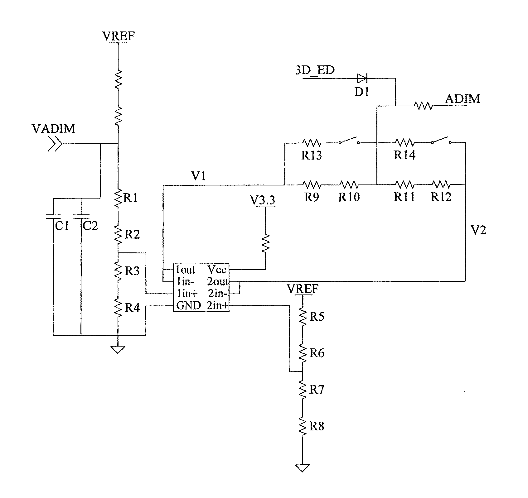
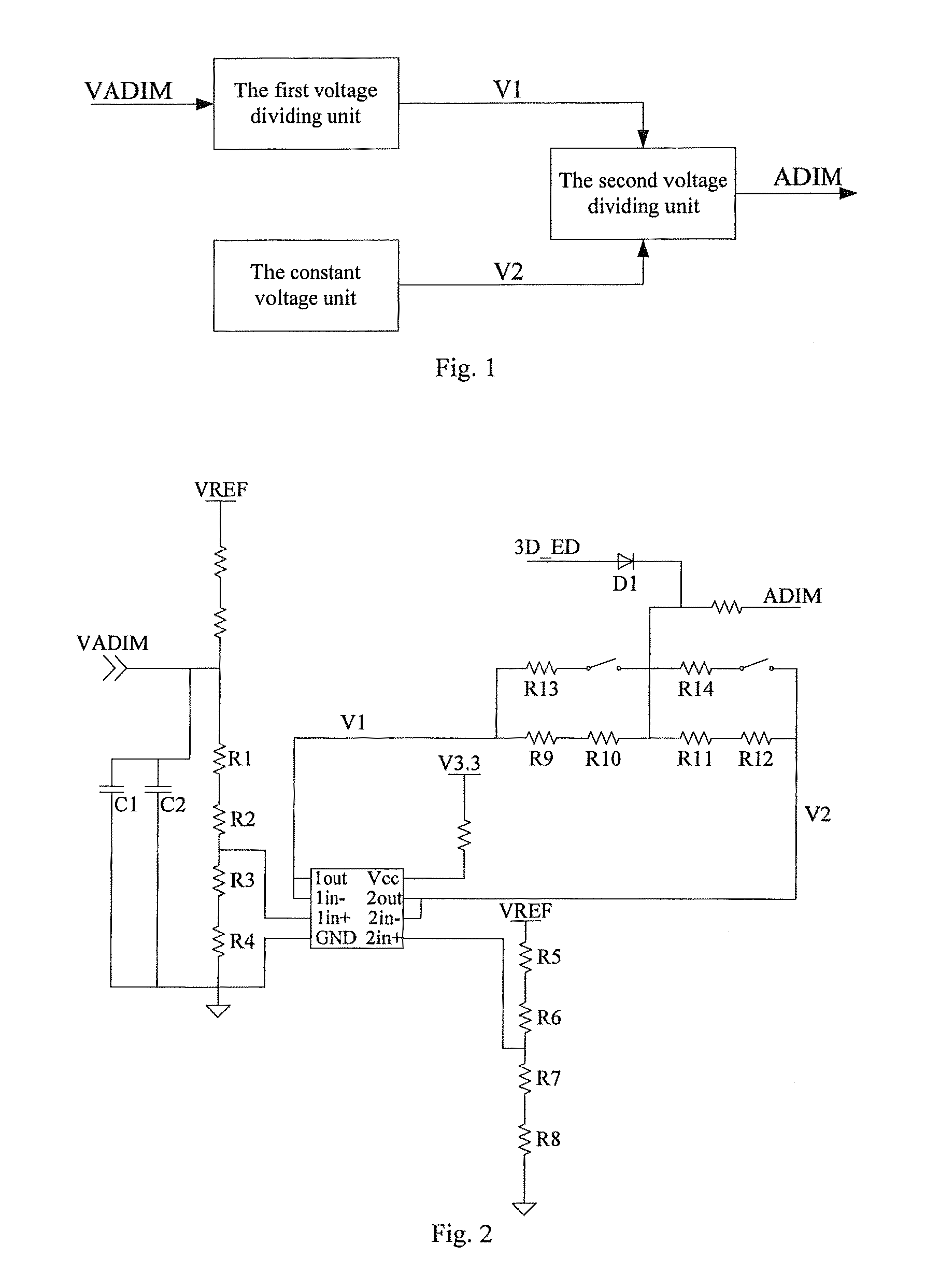
[0020]As shown in FIG. 1, the analog dimming conversion circuit comprises a first voltage dividing unit, a second voltage dividing unit, and a constant voltage unit.

[002...


PUM


Abstract

An analog dimming conversion circuit includes a first voltage dividing unit, a second voltage dividing unit, and a constant voltage unit. An input end of the first voltage dividing unit receives an analog dimming input signal. An output end of the first voltage dividing unit outputs a first intermediate voltage. An output end of the constant voltage unit outputs a second intermediate voltage which is constant. A first input end and a second input end of the second voltage dividing unit receive the first intermediate voltage and the second intermediate voltage respectively. An output end of the second voltage dividing unit outputs an analog dimming output signal. The analog dimming conversion circuit of the present disclosure can be used in liquid crystal TV, liquid crystal display, mobile phone, tablet personal computer, and other display devices with analog dimming function.

Description

CROSS REFERENCE TO RELATED APPLICATION[0001]The present application claims benefit of Chinese patent application CN 201410559611.X, entitled “Analog Dimming Conversion Circuit and Display Device” and filed on Oct. 20, 2014, which is incorporated herein by reference.FIELD OF THE INVENTION[0002]The present disclosure relates to the technical field of display, and particularly to an analog dimming conversion circuit and a display device.BACKGROUND OF THE INVENTION[0003]With the development of display technology, liquid crystal display has become the most commonly used display device. Currently, more and more Light-Emitting Diodes (LED) are used in the liquid crystal display as the backlight source. Moreover, it is hoped that the brightness of the LED can be changed according to different application circumstances. Therefore, the driver of the LED should have the function of brightness adjustment.[0004]Compared with traditional PWM Dimming technology, the Analog Dimming (ADIM) technolog...

Claims


Application Information

Patent Timeline
Patent Type & Authority Patents(United States)
IPC IPC(8): H05B37/02H05B33/08H05B39/04H05B44/00
CPCH05B33/0845H05B45/10H05B45/14
Inventor ZHANG, XIANMING
Owner TCL CHINA STAR OPTOELECTRONICS TECH CO LTD
Why Eureka
Try Eureka