Synchronous boost-buck device and synchronous buck-buck method thereof

A technology for synchronizing buck-boost and output voltage, applied in the buck-boost field, can solve the problems that the voltage value of boost and buck cannot be accurately controlled, does not meet the requirements of miniaturization of electronic products, and is inconvenient for product debugging and maintenance. Simplified design and manufacturing process, good scalability and repeatability, and good dynamic response characteristics

Inactive Publication Date: 2011-04-06
SHENZHEN JINGQUANHUA ELECTRONICS
View PDF5 Cites 11 Cited by
  • Summary
  • Abstract
  • Description
  • Claims
  • Application Information

AI Technical Summary

Problems solved by technology

As we all know, the step-up module and the step-down module contain many electronic components, which need to occupy a certain area on the circuit board, which does not meet the requirements of miniaturization of electronic products, and the step-up or step-down is controlled by hardware, which has poor flexibility. The voltage value of step-up and step-down cannot be precisely controlled and cannot meet the actual working needs
[0004] Moreover, the price of the control chip used in the above-mentioned step-up / down device is relatively high, and there are many electronic components, which makes the cost of the product higher, reduces the competitiveness of the product in the market, and is inconvenient for product debugging and maintenance.

Method used


Image

  • Synchronous boost-buck device and synchronous buck-buck method thereof
  • Synchronous boost-buck device and synchronous buck-buck method thereof
  • Synchronous boost-buck device and synchronous buck-buck method thereof

Examples


Embodiment Construction

[0028] The present invention provides a synchronous buck-boost device and its method for realizing synchronous buck-boost. In order to make the purpose, technical solution and effect of the present invention clearer and more definite, the present invention will be further described in detail below with reference to the accompanying drawings and examples. It should be understood that the specific embodiments described here are only used to explain the present invention, not to limit the present invention.

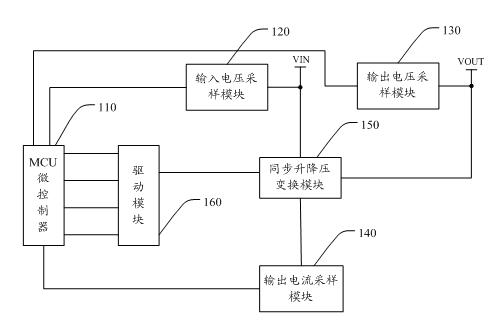
[0029] see figure 1 , The synchronous buck-boost device provided by the present invention includes an MCU microcontroller 110 (Micro Control Unit, micro control unit), an input voltage sampling module 120, an output voltage sampling module 130, an output current sampling module 140 and a synchronous buck-boost conversion module 150.

[0030] The MCU microcontroller 110 is respectively connected with the input voltage sampling module 120, the output voltage sampling module 1...


PUM


Abstract

The invention discloses a synchronous boost-buck device and a synchronous buck-buck method thereof. The synchronous boost-buck device comprises an MCU (Microprogrammed Control Unit), an input voltage sampling module, an output voltage sampling module, an output current sampling module and a synchronous boost-buck conversion module, wherein the MCU is respectively connected with the input voltage sampling module, the output voltage sampling module, the output current sampling module and the synchronous boost-buck conversion module, the input voltage sampling module and the output voltage sampling module are respectively connected with an input port and an output port of the device, and the synchronous boost-buck conversion module is respectively connected with the input port, the output port and the output current sampling module. In the invention, the synchronous boost-buck conversion module is started for boosting or bucking or first boosting and then bucking through an input voltage acquired by the input voltage sampling module, and meanwhile, the synchronous boost-buck conversion module is controlled to output a corresponding voltage value and a corresponding current value according to an output voltage and an output current so as to satisfy the power supply needs of portable equipment.

Description

technical field [0001] The invention relates to voltage-boosting technology, in particular to a synchronous voltage-boosting device and a method for realizing synchronous voltage-boosting. Background technique [0002] High-power portable devices, such as portable medical devices and notebook computers, generally have a DC / DC power supply (DC-to-DC power supply) or a charging management module, so a step-up / down device is usually required in such devices. [0003] The step-up / step-down device controlled by software generally controls separate hardware step-up modules and step-down modules through software, and enables selection of the step-up module or step-down module through the control chip. As we all know, the step-up module and the step-down module contain many electronic components, which need to occupy a certain area on the circuit board, which does not meet the requirements of miniaturization of electronic products, and the step-up or step-down is controlled by hardw...

Claims


Application Information

Patent Timeline
Patent Type & Authority Applications(China)
IPC IPC(8): H02M3/10H02M3/158
Inventor 刘建飞谢春华李战功鞠万金汪兆华
Owner SHENZHEN JINGQUANHUA ELECTRONICS
Why Eureka
Try Eureka