Electrical power system with high-density pulse width modulated (PWM) rectifier

a pulse width modulation and rectifier technology, applied in the direction of dc circuits to reduce harmonics/ripples, power conversion systems, electrical apparatus, etc., can solve the problems of low frequency dc ripple voltage on the dc bus, adversely affect the power density of the rectifier system, etc., to achieve increased power density, improved power density, and improved power density

Active Publication Date: 2013-10-29
VIRGINIA TECH INTPROP INC +1
View PDF13 Cites 11 Cited by
  • Summary
  • Abstract
  • Description
  • Claims
  • Application Information

AI Technical Summary

Benefits of technology

[0005]The present invention provides a single phase PWM rectifier for providing power to a direct current (DC) load that may have an increased power density relative to previous systems. The power density may be increased by employing an auxiliary storage circuit in conjunction with the DC link capacitor. In one embodiment, the auxiliary storage circuit may include an auxiliary capacitor as a storage device that operates across a larger voltage range than does the DC link capacitor. This auxiliary storage device may operate across a larger voltage range because it is not limited by the voltage requirements for the DC bus. Because the auxiliary storage device may operate across a larger voltage range, it may be more efficient at storing the ripple energy, and hence may have a smaller volume than a DC link capacitor that may be otherwise used to store the ripple energy, which may thus increase the power density of the rectifier system.

Problems solved by technology

The ripple power is generally twice the AC input frequency and can therefore cause low frequency DC ripple voltage on the DC bus.
Although various schemes to reduce or eliminate the ripple component have been proposed, most such schemes adversely affect the power density of the rectifier system.

Method used


Image

  • Electrical power system with high-density pulse width modulated (PWM) rectifier
  • Electrical power system with high-density pulse width modulated (PWM) rectifier
  • Electrical power system with high-density pulse width modulated (PWM) rectifier

Examples


Embodiment Construction

[0012]For purposes of promoting an understanding of the principles of the invention, reference will now be made to the embodiments illustrated in the drawings, and specific language will be used to describe the same. It will nonetheless be understood that no limitation of the scope of the invention is intended by the illustration and description of certain embodiments of the invention. In addition, any alterations and / or modifications of the illustrated and / or described embodiment(s) are contemplated as being within the scope of the present invention. Further, any other applications of the principles of the invention, as illustrated and described herein, as would normally occur to one skilled in the art to which the invention pertains, are contemplated as being within the scope of the present invention.

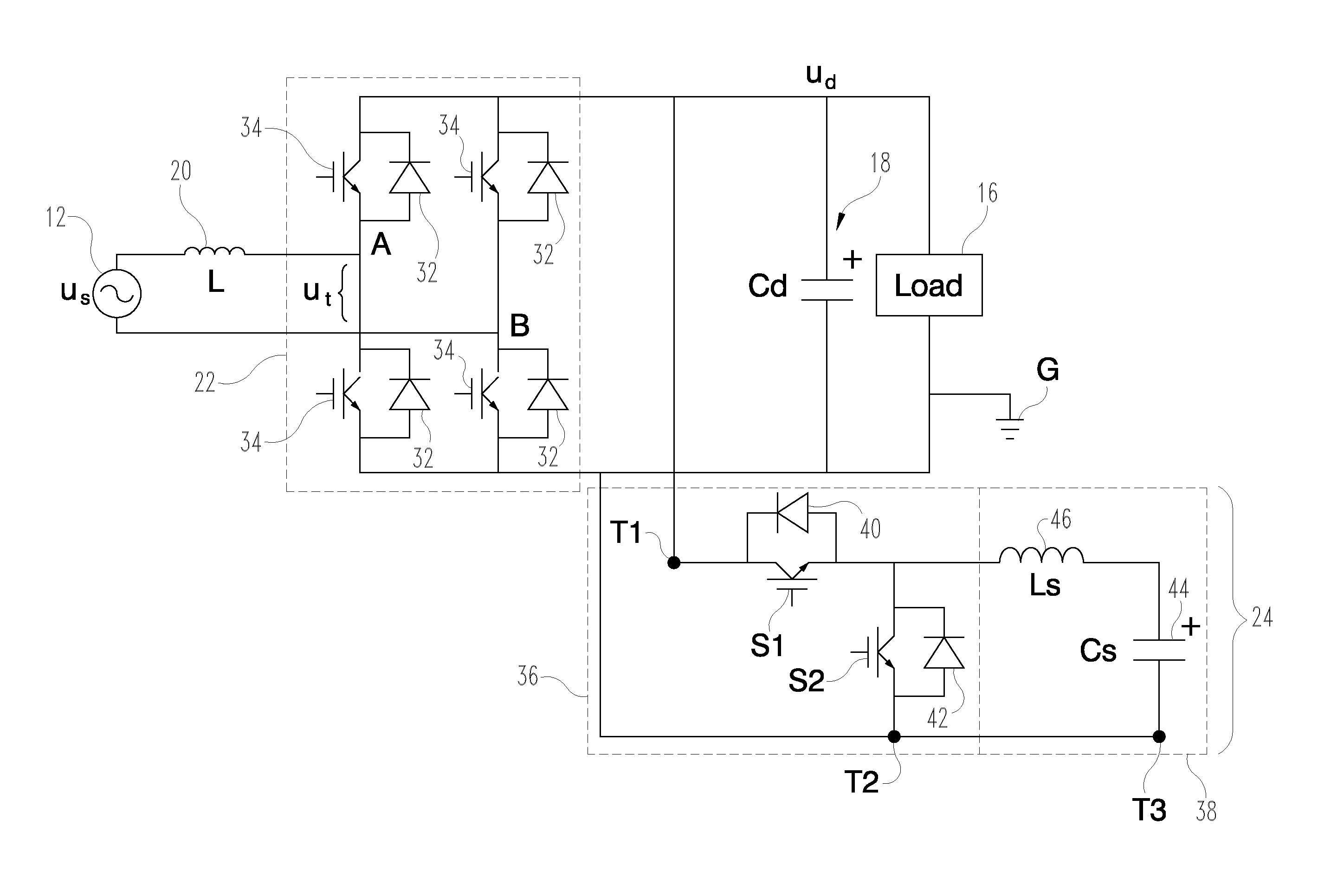
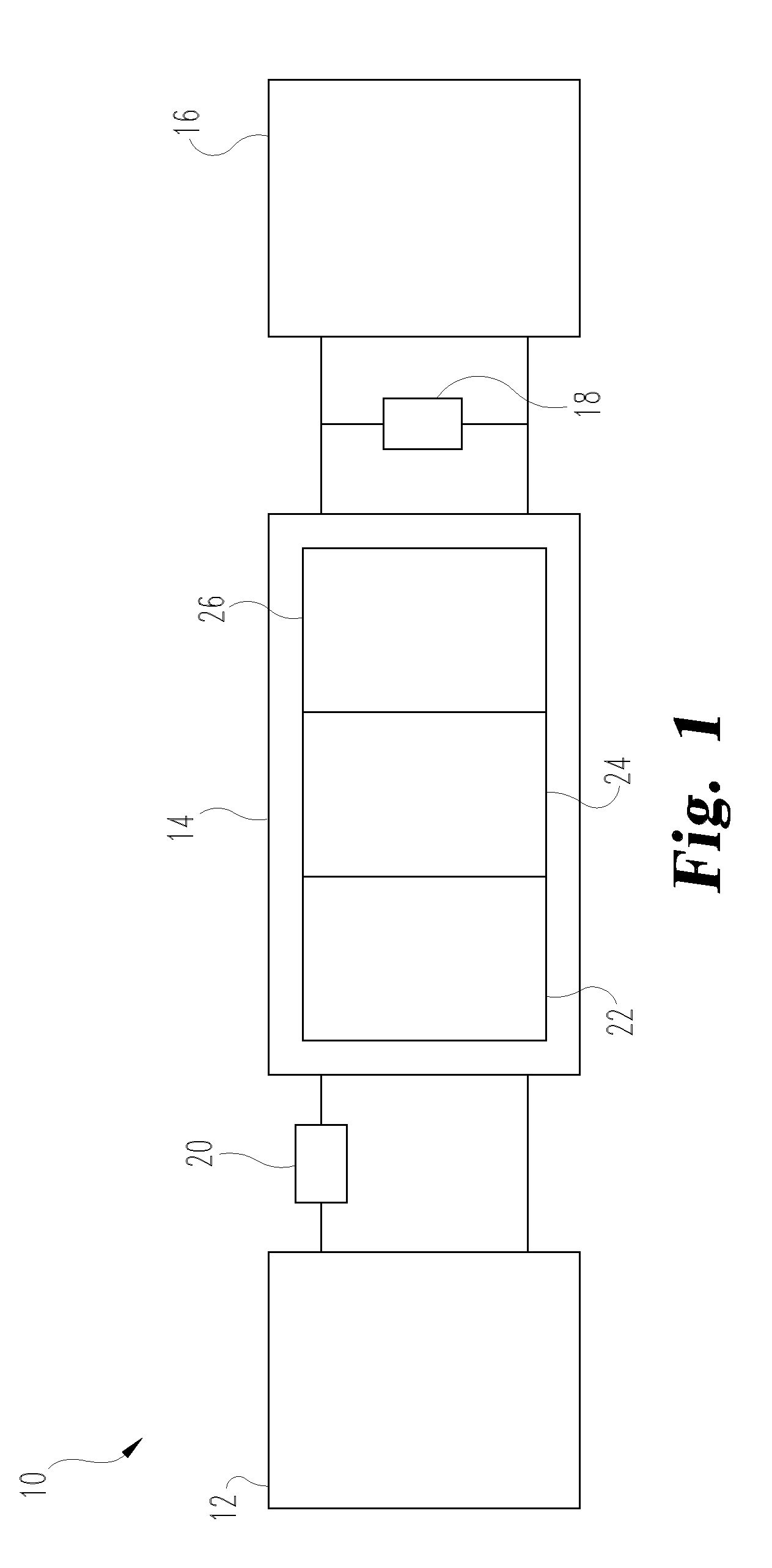
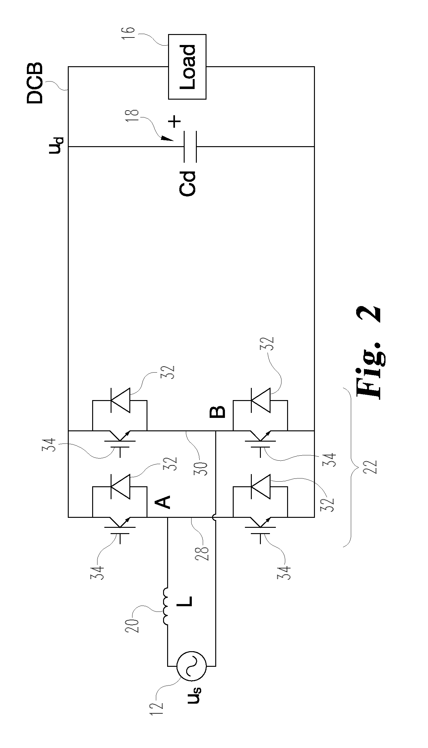
[0013]Referring now to the drawings, and particularly to FIG. 1, there is schematically shown a non-limiting embodiment of an electrical power system 10 in accordance with the present...


PUM


Abstract

An electrical power system includes an alternating current (AC) power source configured to output an AC signal, a single phase pulse-width modulated (PWM) rectifier coupled to the AC power source and to an electrical load; a DC link capacitor coupled in parallel to the load and the PWM rectifier; and an active ripple energy storage circuit. The active ripple energy storage circuit has a first terminal, a second terminal and a third terminal, the active ripple energy storage circuit being coupled in parallel to the electrical load, the PWM rectifier and the DC link capacitor via the first terminal and the second terminal, the third terminal being coupled to the second terminal, the active ripple energy storage circuit being configured to selectively absorb and discharge at least part of the ripple energy.

Description

CROSS REFERENCE TO RELATED APPLICATIONS[0001]The present application claims benefit of U.S. Provisional Patent Application No. 61 / 137,430 filed Jul. 30, 2008, entitled ELECTRICAL POWER SYSTEM WITH HIGH-DENSITY PULSE WIDTH MODULATED (PWM) RECTIFIER, which is incorporated herein by reference.FIELD OF THE INVENTION[0002]The present invention relates to converting alternating current (AC) power to direct current (DC) power to operate an electrical load, and, more particularly, to a high-density pulse width modulated (PWM) rectifier.BACKGROUND[0003]A characteristic of a typical single-phase pulse width modulated (PWM) rectifier is the formation of ripple power on the direct current (DC) link, e.g., where the alternating current (AC) input voltage and current are sinusoidal. The ripple power is generally twice the AC input frequency and can therefore cause low frequency DC ripple voltage on the DC bus. Although various schemes to reduce or eliminate the ripple component have been proposed...

Claims


Application Information

Patent Timeline
Patent Type & Authority Patents(United States)
IPC IPC(8): H02M1/12
CPCH02M1/15H02M7/219
Inventor WANG, RUXIWANG, FREDBURGOS, ROLANDOBOROYEVICH, DUSHANRAJASHEKARA, KAUSHIKLONG, STEPHEN A.
Owner VIRGINIA TECH INTPROP INC
Why Eureka
Try Eureka