[0014]Storing energy in the form of compressed gas has a long history and components tend to be well tested, reliable, and have long lifetimes. The general principles for compressed gas energy storage are the storage of original generated energy in terms of pressure
potential energy by compression of gas and subsequent recovery of energy in useful form through expansion of the gas. Advantages to compressed gas energy storage include low specific-energy costs, long lifetime, low maintenance, reasonable
energy density, and good reliability.
[0015]If the
gas expansion occurs slowly relative to the rate at which heat flows into the gas, then the gas remains at a relatively constant temperature as it expands (isothermal
gas expansion). Gas stored at ambient temperature and expanded isothermally recovers approximately three times the energy of ambient-temperature gas expanded adiabatically. Therefore, there is a significant energy
advantage to expanding gas isothermally.
[0017]The
power output of the
system described in the '057 application is governed by how fast the gas expands isothermally. Therefore, the ability to expand / compress the gas isothermally at a faster rate will result in a greater
power output of the system. By adding a heat-transfer circuit to the system described in the '057 application, the
power density of said system can be increased substantially. Novel heat-transfer circuits are shown and described in U.S.
patent application Ser. No. 12 / 639,703 (the '703 application), entitled SYSTEMS AND METHODS FOR
ENERGY STORAGE AND
RECOVERY USING RAPID ISOTHERMAL
GAS EXPANSION AND COMPRESSION, the disclosure of which is hereby incorporated by reference herein in its entirety. By incorporating a
variable displacement hydraulic-pneumatic pump / motor, the efficiency of the compressed gas energy storage and recovery system may be further improved, as described in U.S.
patent application Ser. No. 12 / 723,084 (the '084 application), entitled SYSTEMS AND METHODS FOR IMPROVING
DRIVETRAIN EFFICIENCY FOR COMPRESSED GAS
ENERGY STORAGE USING STAGED HYDRAULIC CONVERSION, the disclosure of which is hereby incorporated by reference herein in its entirety.
[0018]The novel
compressed air energy storage and recovery systems using staged hydraulic conversion described in the '057 application include a
hydraulic pump / motor which is driven by or used to pump
hydraulic fluid over a range of pressures, i.e., from a mid-pressure to a
high pressure (e.g., 300 psi to 3000 psi). For a typical such expansion or compression over a
pressure range, using a fixed displacement
hydraulic motor, as pressure drops, torque and power drop. In many instances, it would be advantageous to minimize these changes in
power level over the
pressure range. For example, efficiency for an
electric motor / generator can vary substantially based on torque and RPM; when the
hydraulic pump / motor in the staged hydraulic conversion described in the '057 application is attached to an
electric motor / generator, it would be advantageous to operate at a
narrow range or fixed value for RPM (e.g., ˜1800 RPM) and torque to operate at peak efficiency, increasing electric-
motor efficiency and thus system efficiency. Likewise, operating at a fixed RPM and power (and thus
constant voltage, frequency, and current for an
electric generator) during system
discharge could allow an
electric generator to be synchronized with the grid and potentially eliminate additional power
conditioning equipment that would be required for a variable frequency, variable
voltage, and / or variable
power output. One method for maintaining a constant or nearly
constant power output over the range of pressures is to use a
variable displacement hydraulic pump / motor in lieu of a constant displacement pump / motor. By using a
variable displacement hydraulic pump / motor, the displacement per revolution can be controlled in such a way as to maintain a nearly
constant torque and proportionally increasing flow rate such that the RPM and power output are kept nearly constant. For the novel
compressed air energy storage and recovery system using staged hydraulic conversion described in the '057 application, this constant RPM and power allows for a reduction in electric system costs by potentially eliminating power
conditioning equipment necessary for a variable frequency,
voltage, or power output, while at the same time improving overall system efficiency by operating at the peak efficiency region of the
electric generator; likewise, increasing flow rate maintains a nearly
constant power throughout a decreasing
pressure range, also adding value to the energy storage and recovery system.
[0044]The invention is also directed toward efficiently utilizing high-pressure compressed air in combination with hydraulic-pneumatic cylinders and a
hydraulic motor to provide the primary means of propulsion for a vehicle, such as an automobile,
truck, boat, or
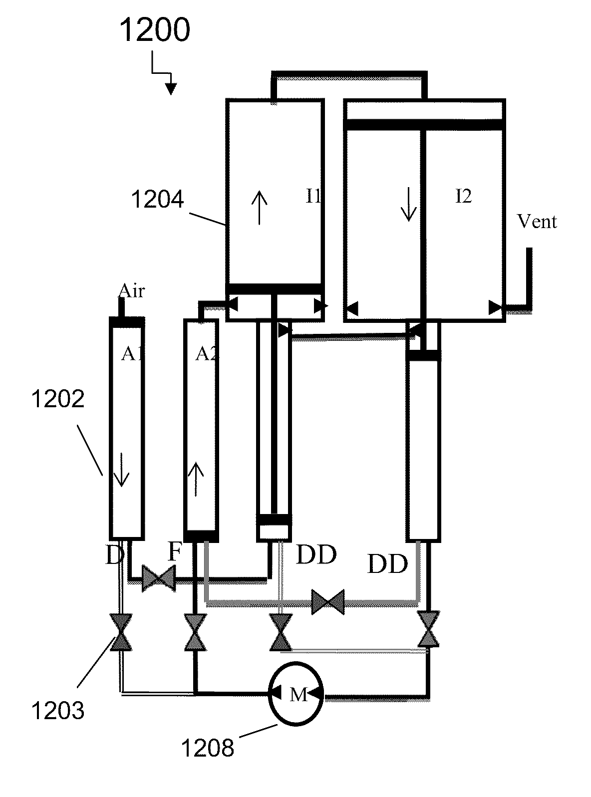
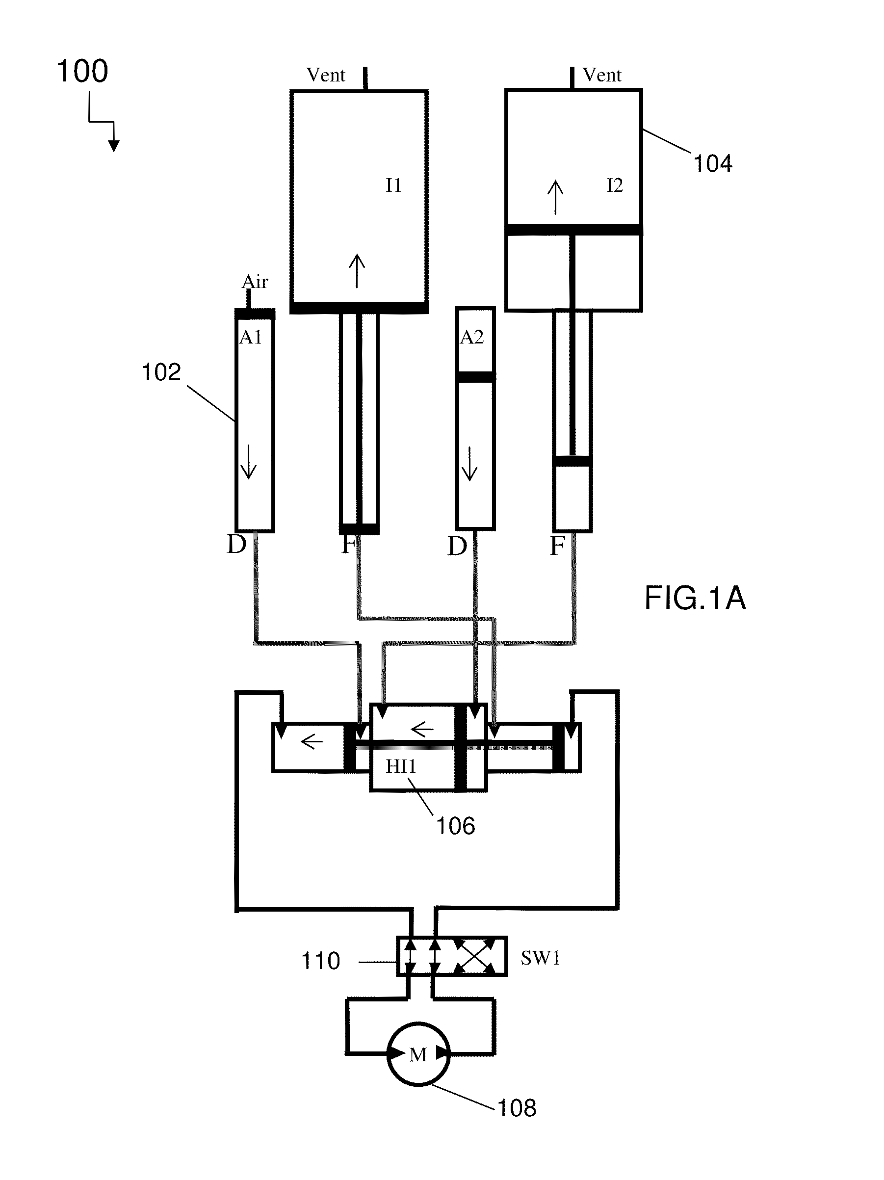
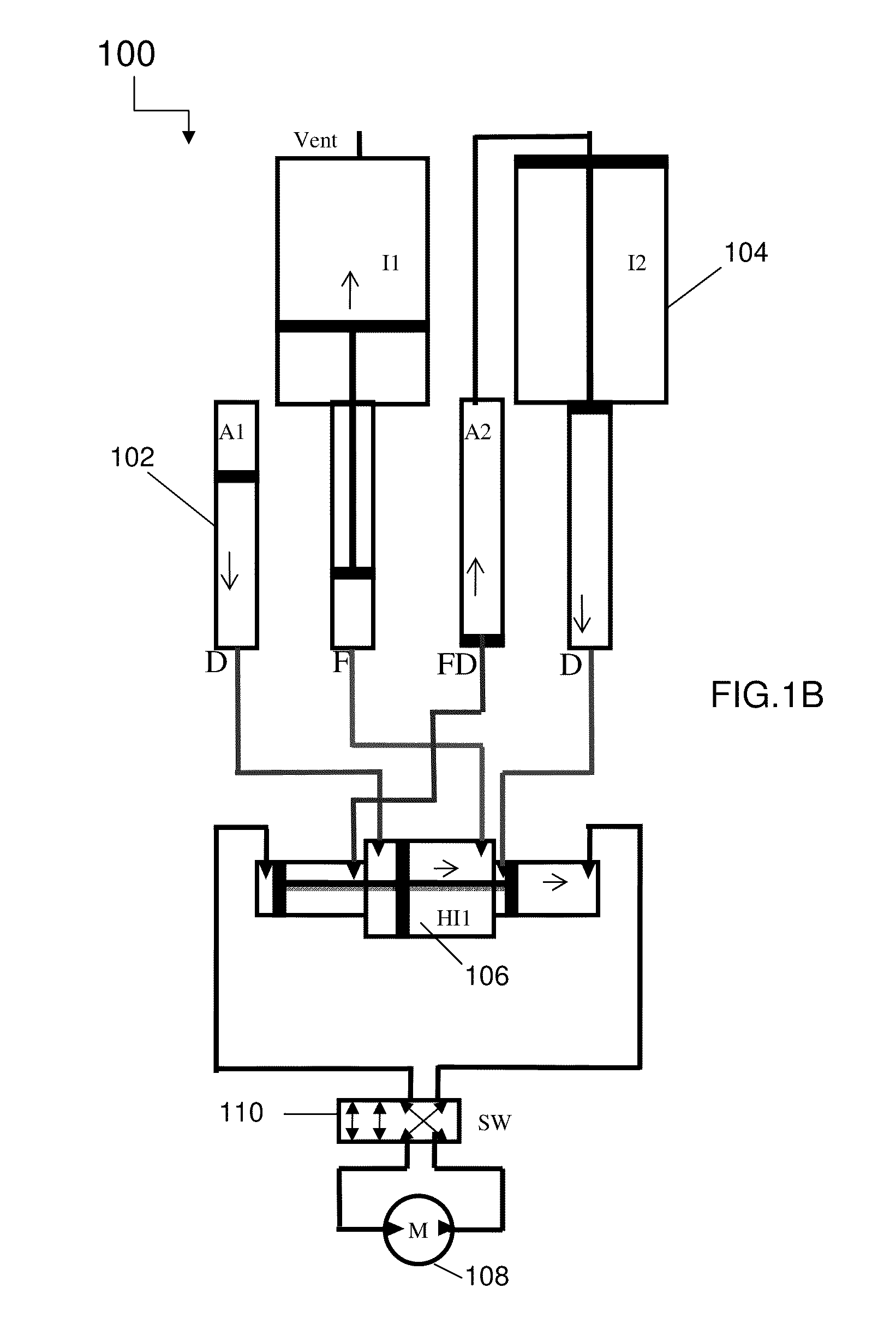
train. Specifically, high-pressure compressed air, stored in pressure vessels, is expanded in batches in hydraulic-pneumatic cylinders, driving high-pressure
hydraulic fluid through a hydraulic motor to provide propulsive force. The compressed air undergoes quasi-isothermal controlled expansion in the hydraulic-pneumatic cylinders, which are integrated with heat exchangers. The hydraulic-pneumatic cylinders may include intensifiers to maintain a high
hydraulic pressure even as the air pressure decreases within each batch expansion. Additional hydraulic boosters may be used to intensify and / or add pressures from multiple expanding cylinders. During braking and coasting, the hydraulic motor may be run in reverse, recompressing the air in the pneumatic-hydraulic cylinders and storing energy from the motion of the vehicle as compressed-air
potential energy. In an alternative embodiment of this application, when the compressed air reaches a lower pressure (e.g., 120 psi), it is expanded in an air-
turbine-based motor attached to the same shaft as the hydraulic motor, thus greatly increasing the
power density of the hydraulic-pneumatic conversion system. In an additional embodiment, the lower-pressure compressed air is used in combination with
compressed natural gas to drive a
turbine-based motor attached to the same shaft as the hydraulic motor, further increasing
power density and
energy density.
[0047]Near-isothermal expansion permits increased round-trip thermodynamic efficiency in the compressed-air energy storage component, e.g., ˜95% versus <40% for an adiabatic system. For the same reason, the
energy density of a near-isothermal system is more than double the energy density of an adiabatic compressed-air storage system. Moreover, with near-isothermal compression and expansion, there is a
nonlinear gain in energy density and power density with increasing maximum storage pressure—e.g., storage at 10,000 psi more than triples (increases ˜3.7 times) energy density over storage at 3,333 psi. In addition, increasing
maximum pressure reduces the amount of energy in each expansion at low pressures, thus reducing any losses that would be associated with the inclusion of a low-pressure air
turbine motor to increase power density, as described in FIG. 33 herein.

