

Wind power and photovoltaic power complementary power supply system based on mixed energy accumulation of super capacitor accumulator
A supercapacitor and hybrid energy storage technology, which is used in electrical energy storage systems, photovoltaic power generation, wind power generation, etc., can solve the problems of high system cost, low service life, and difficulty in output, achieve fast charging and discharging speed, and prolong service life. , the effect of reducing the installation capacity
- Summary
- Abstract
- Description
- Claims
- Application Information
AI Technical Summary
Problems solved by technology
Method used
Image

Examples
Embodiment Construction
[0033] The present invention will be further described below in conjunction with the accompanying drawings and specific embodiments.
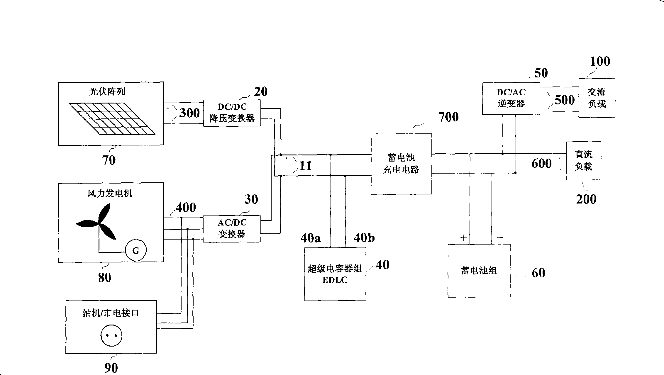
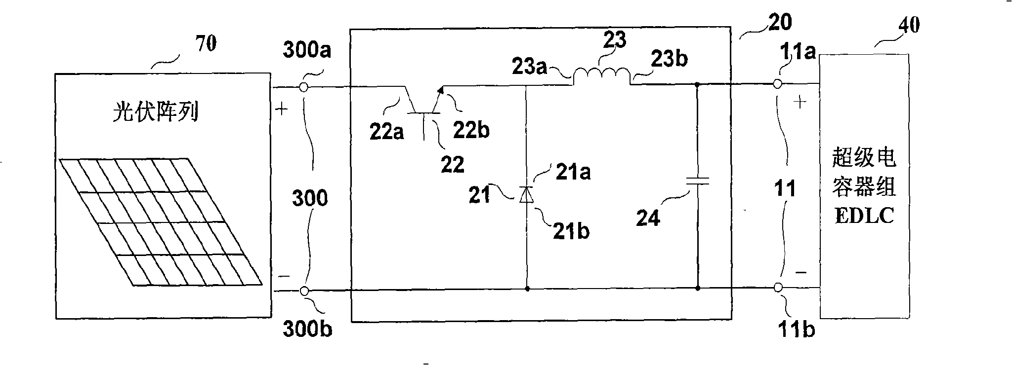
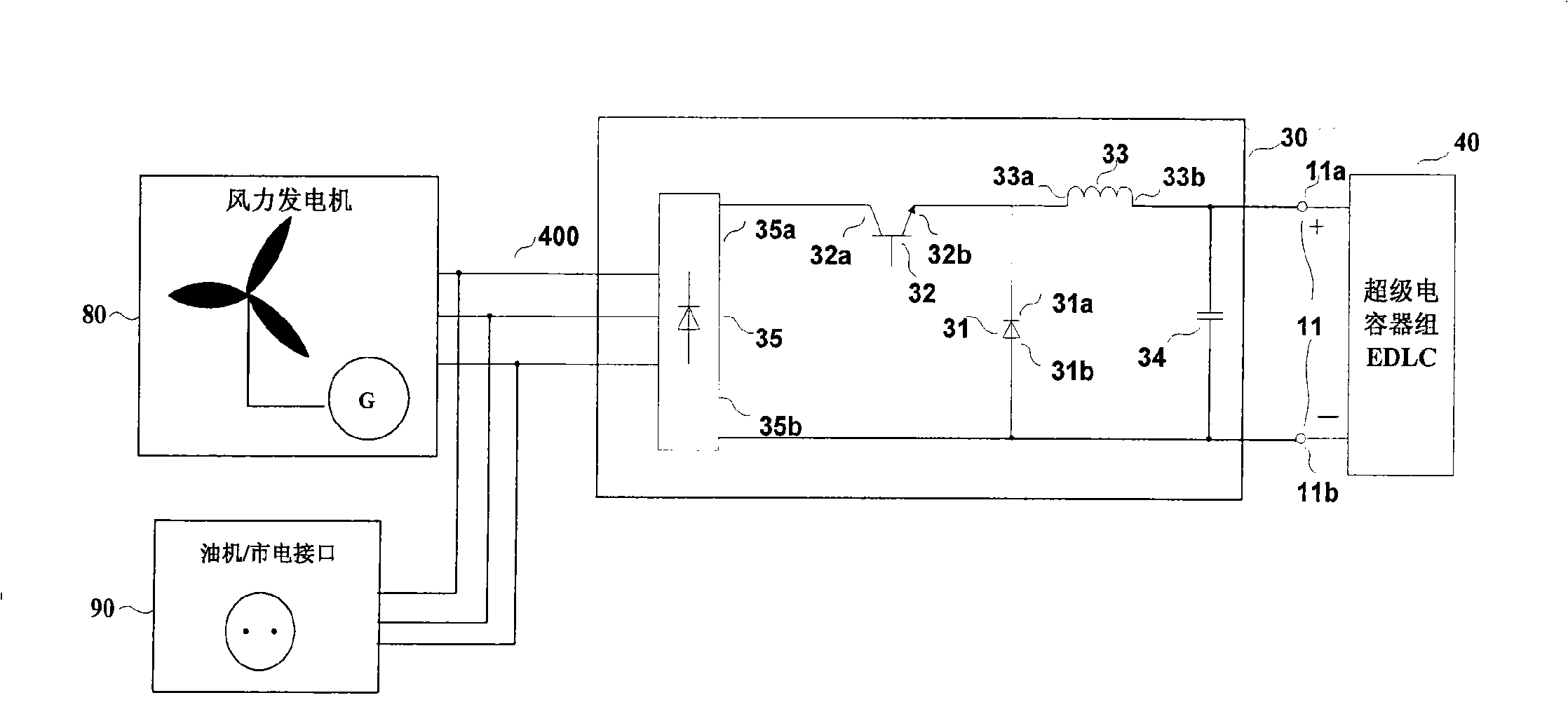
[0034] figure 1 Shown is an embodiment of the wind power generation and photovoltaic power generation complementary power supply system based on supercapacitor battery hybrid energy storage of the present invention. This embodiment includes a DC bus 11, a DC / DC step-down converter 20, an AC / DC converter 30, a supercapacitor bank 40, a DC / AC inverter 50, a battery pack 60, a battery charging circuit 700, and a photovoltaic array 70, Wind power generator 80 , diesel engine / mains interface 90 , photovoltaic power generation output 300 , wind power generation output 400 , AC load port 500 , DC load port 600 , AC load 100 and DC load 200 . The DC bus 11 is connected to the supercapacitor bank 40, the photovoltaic array 70 is connected to the supercapacitor bank 40 through the DC / DC step-down converter 20, and the photovoltaic power generation outpu...
PUM
 Abstract
Description
Claims
Application Information