Device and method for boosting network voltage at tail end of electrified railway power supply arm

A technology for electrified railways and power supply arms, which is applied in AC network voltage adjustment, flexible AC transmission system, reactive power compensation, etc., and can solve problems such as inability to realize dynamic tracking compensation, reactive power over-compensation and under-compensation, and large load fluctuations , to achieve the effect of ensuring the passing capacity of the line, stabilizing the network voltage of the power supply arm, and reducing the installation capacity

Active Publication Date: 2011-10-19
ZHUZHOU NAT ENG RES CENT OF CONVERTERS
View PDF4 Cites 10 Cited by
  • Summary
  • Abstract
  • Description
  • Claims
  • Application Information

AI Technical Summary

Problems solved by technology

Due to the large load fluctuation at the end of the power supply arm of the electrified railway, if only FC devices or MSC and TSC graded switching devices are used, the switching frequency

Method used


Image

  • Device and method for boosting network voltage at tail end of electrified railway power supply arm
  • Device and method for boosting network voltage at tail end of electrified railway power supply arm
  • Device and method for boosting network voltage at tail end of electrified railway power supply arm

Examples


Example Embodiment

[0032] Implementation mode one:

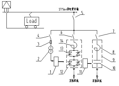
[0033] As attached figure 2 As shown, a specific implementation of the device and method for increasing the grid voltage at the end of the electric railway power supply arm of the present invention consists of the FC device 9, the dynamically adjustable reactive power source 12, and the voltage transformer 2 in parallel, and through the switch device 5. It is directly connected to the end of the 27.5kv power supply arm. The FC device 9 and the dynamically adjustable reactive power source 12 adopt a rail return method to return the equipment current to the main transformer of the traction substation.

[0034] The dynamic adjustable reactive power source 12 in a specific implementation of the device for increasing the grid voltage at the end of the electric railway power supply arm adopts a direct-mounted TCR device, which is mainly composed of a thyristor valve 13 and a phase-controlled reactor 14. The thyristor valve 13 is formed by connecting se...

Example Embodiment

[0038] Implementation mode two:

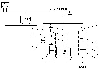
[0039] As attached image 3 As shown, another specific implementation of the device for increasing the grid voltage at the end of the electric railway power supply arm of the present invention consists of the FC device 9, the dynamically adjustable reactive power source 12, and the voltage transformer 2 in parallel, and through the switch device 5 The end of the 27.5kv power supply arm is directly connected. The FC device 9 and the dynamically adjustable reactive power source 12 adopt a rail return method to return the equipment current to the main transformer of the traction substation.

[0040] The dynamic adjustable reactive power source 12 in a specific implementation of the device for increasing the grid voltage at the end of the electric railway power supply arm adopts an SVG device, which is mainly composed of an IGBT module 15, a reactor 16 and a transformer 17. The transformer reduces the voltage of the contact network from 27.5kv to 10k...


PUM


Abstract

The invention discloses a device and a method for boosting network voltage at the tail end of an electrified railway power supply arm. A network voltage boosting device is assembled at the tail end of a power supply arm in a traction substation, and the reactive current of a load is dynamically compensated on site; therefore, the circuit network voltage is boosted. A fixed capacitor (FC) device, a dynamically adjustable reactive source and a voltage transformer are connected in parallel; the dynamically adjustable reactive source and the FC device are matched to dynamically track and compensate the reactive current of the load on site; the dynamically adjustable reactive source realizes stepless and non-contact switching and controls the reactive capacity of output; the FC device comprises a filter reactor and a capacitor bank which are connected in series; and a secondary side of the voltage transformer is connected with a controller. By the device and the method, the problems that atransmission line has lower efficiency and an optimized network voltage boosting effect cannot be achieved due to relatively high equipment mounting capacity of a compensation device arranged in the substation and the reactive current because of long power supply arm and high line impedance are solved, the network voltage boosting device is not limited by a space position of the traction substation, the investment is low, and the construction period is short.

Description

technical field [0001] The invention relates to a power quality control device, in particular to a device and method for increasing network voltage at the end of an electrified railway power supply arm, which is mainly used in rail transit power transmission and distribution systems. Background technique [0002] With the acceleration of the development of high-speed and heavy-duty railways in my country, the traffic volume of railway lines is increasing day by day. Due to the influence of terrain and terrain, the layout of traction substations in many electrified operation sections is far away, making traction with large slopes The grid voltage is too low (lower than 19kv), causing parking accidents and seriously affecting the transportation capacity of the line. [0003] At present, the solution to the low voltage of the traction network generally adopts methods such as expanding the capacity of the transformer, increasing the diameter of the distribution line, changing the...

Claims


Application Information

Patent Timeline
IPC IPC(8): H02J3/16H02J3/18
CPCY02E40/10Y02E40/30
Inventor 石二磊黄燕艳周方圆段世彦周靖唐建宇余军吴明水文韬邱文俊朱建波易海泉胡前吴选宝王桂华蔡蔚
Owner ZHUZHOU NAT ENG RES CENT OF CONVERTERS
Why Eureka
Try Eureka