Capacitance energy-storage type relay circuit

A relay circuit and capacitive energy storage technology, which is applied to relays, circuits, electrical components, etc., can solve the problem of large waste of electric energy

Inactive Publication Date: 2006-02-22
陈俊峰
View PDF0 Cites 10 Cited by
  • Summary
  • Abstract
  • Description
  • Claims
  • Application Information

AI Technical Summary

Problems solved by technology

Since the electromagnetic coils in the prior art are operated at ≥70% of the rated voltage of the electromagnetic coils when the relay is engaged and maintained, it is obvious that the electric energy is wasted a lot

Method used


Image

  • Capacitance energy-storage type relay circuit
  • Capacitance energy-storage type relay circuit
  • Capacitance energy-storage type relay circuit

Examples


Embodiment Construction

[0011] The present invention will be described in further detail below in conjunction with the accompanying drawings.

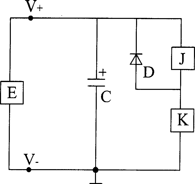
[0012] figure 1 A capacitive energy storage relay circuit of the present invention includes: a pulsed DC power supply E, a capacitor C, a relay J, a diode D, and a control switch K. The pulsed DC power supply E can be a pulsed DC voltage output with an arbitrary waveform, and its positive and negative output terminals V+, V- are connected to the positive and negative poles of the capacitor C correspondingly; the capacitor C is an energy storage and filter capacitor; the relay J After being connected in series with the control switch K, it is connected in parallel with the V+ and V- terminals of the pulsed DC power supply E; the cathode of the diode D is connected to the V+ terminal of the pulsed DC power supply E, and the anode is connected to the series connection point of the relay J and the control switch K .

[0013] When the control switch K is turned ...


PUM


Abstract

Disclosed an energy-saving relay circuit, comprises impulsion direct current power source E, capacitor C, relay J, diode D, and pilot switch K. Wherein, the impulsion direct current power source can charge the capacitor C when the pilot switch K is opened, and control the relay J close when the pilot switch is closed; since the limitation of efficient output power of impulsion direct current power source, the closed relay J will work in a low voltage to maintain the adherent; the impulsion direct current power source E will charge the capacity C repeatedly when the pilot switch K is opened, to operate the on-off operation repeatedly for energy saving.

Description

technical field [0001] The invention relates to relays, in particular to energy-saving application circuits of various electromagnetic relays. Background technique [0002] In the current existing technology, according to the various relay parameters given in the first edition of the "Practical Handbook of New Relays" published by the People's Posts and Telecommunications Press in June 2004, it can be known that the pull-in voltage of the DC relay is ≥ 70% of the rated voltage of the electromagnetic coil , to maintain the pull-in voltage ≥ 10% of the rated voltage of the electromagnetic coil, the pull-in voltage of the AC relay ≥ 80% of the rated voltage of the electromagnetic coil, and to maintain the pull-in voltage ≥ 30% of the rated voltage of the electromagnetic coil, while the AC relay is applied in a DC circuit with DC The characteristics of the relay are similar. For example: a relay with an internal resistance of R pulls under the rated DC voltage U of its solenoid...

Claims


Application Information

Patent Timeline
Patent Type & Authority Applications(China)
IPC IPC(8): H01H47/02
Inventor 陈俊峰
Owner 陈俊峰
Why Eureka
Try Eureka