Parts attaching structure

a technology of parts and structures, applied in the direction of screws, threaded fasteners, snap fasteners, etc., can solve the problems of clip rattle, new clip molded each time the thickness of the first part is increased, and the clip is reluctant to turn, so as to achieve the effect of reducing the turning motion of the clip

Active Publication Date: 2010-07-13
PIOLAX CO LTD
View PDF15 Cites 11 Cited by
  • Summary
  • Abstract
  • Description
  • Claims
  • Application Information

AI Technical Summary

Benefits of technology

[0009]Therefore, an object of the invention is to provide a parts attaching structure, which can attach a clip firmly to apart without being influenced by the thickness of the part and which can prevent the clip reliably from coming out from the part without deteriorating the attachment of the clip.
[0023]Moreover, the second flange portion comes into elastic abutment against the peripheral edge of the back side of the slot, so that the first flange portion comes into close contact with the first part. As a result, the engaging force between the first flange portion and the protrusions of the first part can be enhanced without making the protrusions high, and the turning motion of the clip can be restricted more effectively without deteriorating the attachment of the clip.

Problems solved by technology

If the thickness of the first part is smaller than the gap between the first and second flange portions, the clip rattles to raise a disadvantage that a new clip has to be molded each time the thickness of the first part varies.
When the clip is turned at the attaching time, however, the protrusions are forced to contact with the back face of the first part thereby to make the clip reluctant to turn.
However, the protrusions do not come, when fitted on the two longitudinal end portions of the slot, into effective engagement with the inner periphery of the slot so that the turning motion is not reliably stopped.
This raises a problem that it is difficult to set the height of the protrusions.
As described above, moreover, the stop of the turning motion of the first part by the clip is insufficient, or the rattling occurs.

Method used


Image

  • Parts attaching structure
  • Parts attaching structure
  • Parts attaching structure

Examples


Embodiment Construction

[0039]One mode of embodiment of a parts attaching structure of the invention is described in the following with reference to FIGS. 1 to 9C.

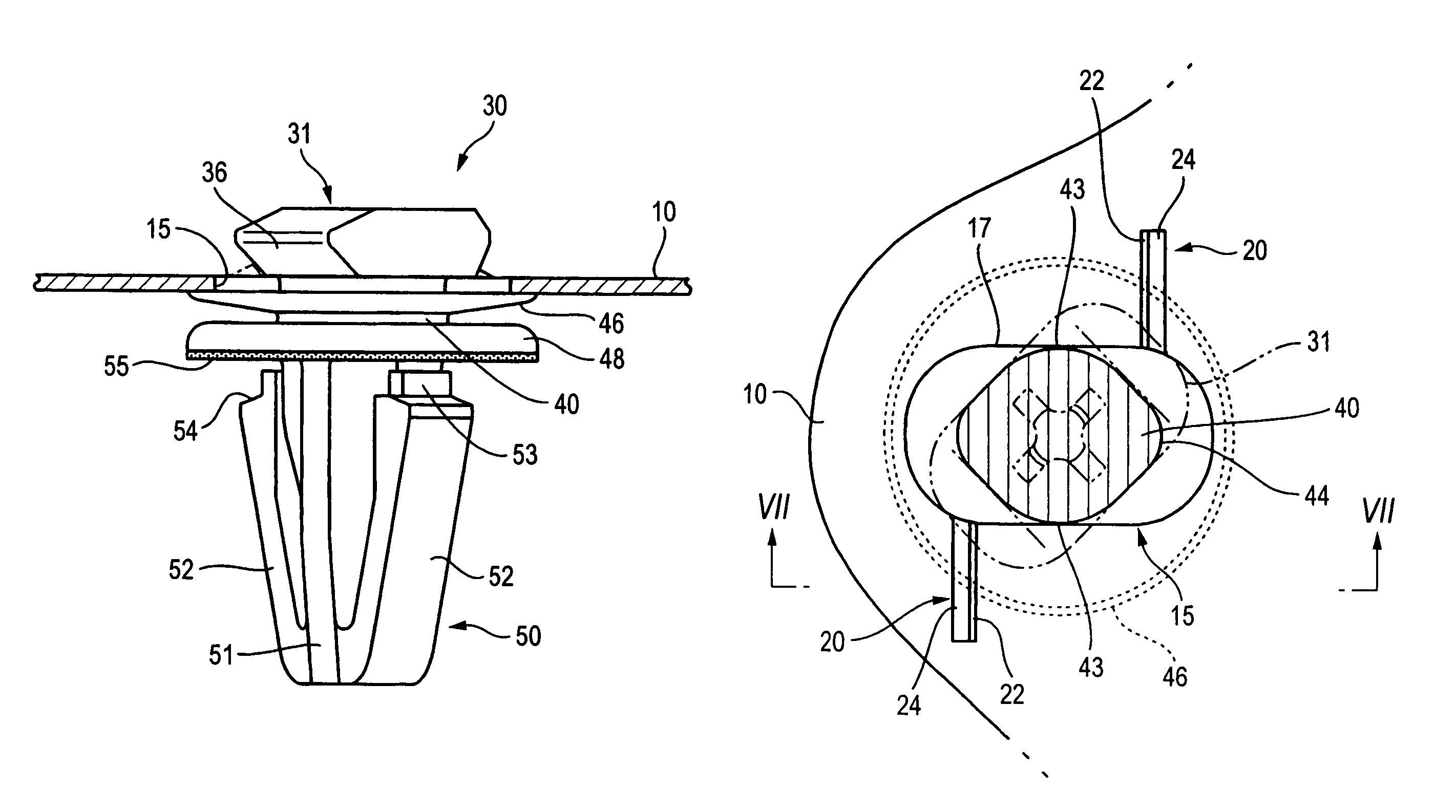
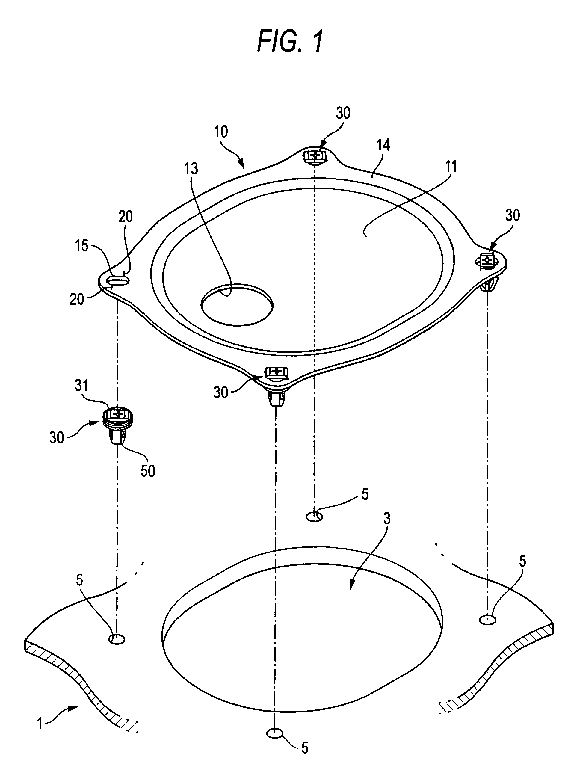
[0040]A fuel tank is arranged below the body panel of an automobile, for example. This fuel tank is connected with parts such as valves or pipes so that it is maintained by inspecting it periodically or by replacing the parts. As shown in FIG. 1, therefore, a panel member 1, as arranged above the fuel tank, has an opening portion 3 called the “maintenance hole”. To this opening portion 3, there is attached a cover member 10 called the “maintenance hole cap”. This mode of embodiment is applied to a structure, which connects the cover member 10 and the panel member 1 through clips 30. Specifically, the cover member 10 makes the first part in the invention, and the panel member 1 makes the second part in the invention. The cover member 10 is formed, at its four peripheral portions, with slots 15 for attaching the clips 30. In the panel member 1, mor...


PUM


Abstract

This attaching structure includes: a first part having a slot; a second part having an attaching hole; and a clip for connecting those parts, the clip including a first flange portion, a shank portion, a second flange portion for coming into elastic abutment against the back side of the slot, a third flange portion, and a leg portion to be retained in the attaching hole, wherein: the shank portion has sliding portions of a large arcuate shape, and stopper portions of a small arcuate shape; protrusions are disposed on the first part in the periphery of the side portions close to the stopper portions when the first flange portion intersects at a right angle with respect to the slot; and the protrusions engage with the first flange portion to stop the turning motion thereby to prevent the clip from coming out from the first part.

Description

BACKGROUND OF THE INVENTION[0001]1. Field of the Invention[0002]The present invention relates to a parts attaching structure, which is applied for attaching a first part such as a cover member for an automobile to a second part such as a panel member of the automobile.[0003]2. Description of the Related Art[0004]As the parts attaching structure of this kind of the prior art, there is disclosed in Japanese Patent No. 3,429,202 a parts attaching structure, in which a clip is attached to a first part (or a first panel-shaped part) having a slot so that the first part is attached to a second part (or a second panel-shaped part) through the clip by bringing the clip into engagement of an attaching hole of the second part. The clip is provided with a first flange portion of a rectangular shape having a longer diameter and a shorter diameter, a disc-shaped second flange portion extending downward from the first flange portion through a shank portion (or a neck portion) extending from the c...

Claims


Application Information

Patent Timeline
Patent Type & Authority Patents(United States)
IPC IPC(8): F16B21/02
CPCF16B5/065F16B21/086F16B21/02Y10T24/4578
Inventor NAKAZATO, HIROSHI
Owner PIOLAX CO LTD
Why Eureka
Try Eureka