Mixing vessel with a fluid-agitating element supported by a roller bearing

a technology of fluid-agitating element and mixing vessel, which is applied in the field of vessels, can solve problems such as environmental pollution danger, contamination or leakage during mixing, and degradation of products, and achieve the effects of reducing the risk of contamination or leakage, reducing the risk of contamination, and reducing the production efficiency

Active Publication Date: 2010-07-27
PALL TECH UK
View PDF116 Cites 35 Cited by
  • Summary
  • Abstract
  • Description
  • Claims
  • Application Information

AI Technical Summary

Problems solved by technology

One significant limitation or shortcoming of such an arrangement is the danger of contamination or leakage during mixing.
This opening provides an opportunity for bacteria or other contaminants to enter, which of course can lead to the degradation of the product.
A corresponding danger of environmental contamination exists in applications involving hazardous or toxic fluids, or suspensions of pathogenic organisms, since dynamic seals or bearings are prone to leakage.
Cleanup and sterilization are also made difficult by the dynamic bearings or seals, since these structures typically include folds and crevices that are difficult to reach.
Despite the advantages of this type of mixing systems and others where the need for a shaft penetrating into the vessel or dynamic seal is eliminated, a substantial, but heretofore unsolved problem with such systems is the difficulty in coupling a fluid-agitating element with an external motive device providing the rotation and / or levitation force.
However, this is considered inconvenient and time consuming, especially if fluid is already present in the bag.
Moreover, in the case where the bag is relatively large (e.g., capable of holding 100 liters or more) or formed of an opaque material, achieving the proper positioning of the fluid-agitating element relative to the external motive device is at a minimum difficult, and in many cases, impossible.
In the absence of fortuity, a significant amount of time and effort is required to lift and blindly reposition the bag relative to the motive device, without ever truly knowing that the coupling is properly formed.
Also, even if the coupling is initially formed, the fluid-agitating element may become accidentally decoupled or disconnected from the motive device during the mixing operation.
In view of the semi-chaotic nature of such an event, the ultimate resting place of the fluid-agitating element is unknown and, in cases where the fluid is opaque (e.g., blood) or cloudy (e.g., cell suspensions), not easily determined.
If the coupling ultimately cannot be established in the proper fashion, the desired fluid agitation cannot be achieved in a satisfactory manner, which essentially renders the set up useless.
These shortcomings may significantly detract from the attractiveness of such fluid agitation systems from a practical standpoint.
While this direct support arrangement prevents the fluid-agitating element from becoming lost in the event of an accidental decoupling, the use of such post or like structure in a bag for receiving and holding a fluid-agitating element has not been proposed.

Method used


Image

  • Mixing vessel with a fluid-agitating element supported by a roller bearing
  • Mixing vessel with a fluid-agitating element supported by a roller bearing
  • Mixing vessel with a fluid-agitating element supported by a roller bearing

Examples


Embodiment Construction

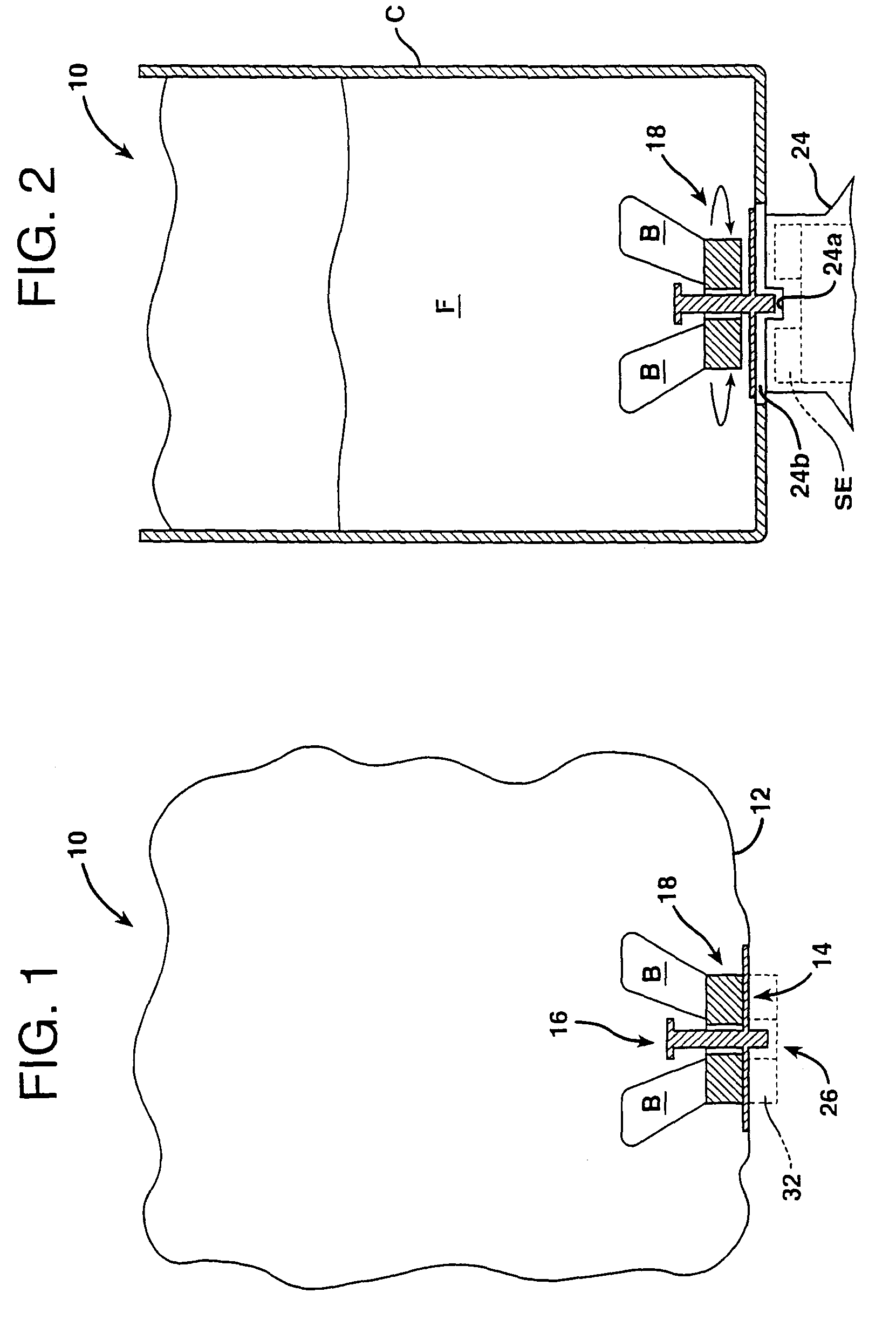
[0045]Reference is now made to FIG. 1, which discloses one embodiment of the vessel of the present invention in the form of a bag 10, which of course is collapsible when empty. In this embodiment, the bag 10 includes a body having a flexible or non-rigid portion 12, which is illustrated schematically, and a rigid or stiff portion 14, which is shown in cross-section. The bag 10 may be hermetically sealed and may have one or more openings or fittings (not shown) for introducing or recovering a fluid. Alternatively, the bag 10 may be unsealed or open-ended. The particular geometry of the bag 10 employed normally depends on the application and is not considered critical to the invention. For example, in the case of a sterile fluid, a hermetically sealed, pre-sterilized bag with an aseptic fitting might be desirable; whereas, in the case where sterility is not important, an open-ended or unsealed bag might be suitable. The main important point is that the bag 10 is capable of receiving a...


PUM


Abstract

In a vessel, such as a flexible bag, a fluid is received and agitated using an internal fluid-agitating element driven by an external motive device and supported by a bearing, such as a roller bearing.

Description

[0001]This application claims the benefit of U.S. Provisional Patent Application Ser. No. 60 / 634,664, filed Dec. 9, 2004, and is a continuation-in-part of U.S. patent application Ser. No. 10 / 491,512, filed Apr. 1, 2004 now U.S. Pat. No. 7,481,572 the disclosures of which are incorporated herein by reference. This application is a continuation-in-part of Ser. No. 10 / 398,946, now U.S. Pat. No. 7,086,778, which is the national stage of PCT / US01 / 31459, filed Oct. 9, 2001, which claims the benefit of the following U.S. Provisional Patent Applications: (a) Ser. No. 60 / 239,187, filed Oct. 9, 2000; (b) Ser. No. 60 / 282,927, filed Apr. 10, 2001; and (c) Ser. No. 60 / 318,579, filed Sep. 11, 2001.TECHNICAL FIELD[0002]The present invention relates generally to vessels in which fluids are agitated and, more particularly, to a collapsible mixing vessel, or bag, including a fluid-agitating element supported by a roller bearing.BACKGROUND OF THE INVENTION[0003]Most pharmaceutical solutions and suspen...

Claims


Application Information

Patent Timeline
Patent Type & Authority Patents(United States)
IPC IPC(8): B01F7/16
CPCB01F7/162B01F13/0827B01F15/00824B01F15/0085C12M23/14C12M27/02B01F7/00858B01F27/41B01F27/808B01F33/453B01F35/50B01F35/513
Inventor TERENTIEV, ALEXANDRE N.TERENTYEV, SERGEY
Owner PALL TECH UK
Why Eureka
Try Eureka