Sizer for a hanger
- Summary
- Abstract
- Description
- Claims
- Application Information
AI Technical Summary
Benefits of technology
Problems solved by technology
Method used
Image
Examples
third embodiment
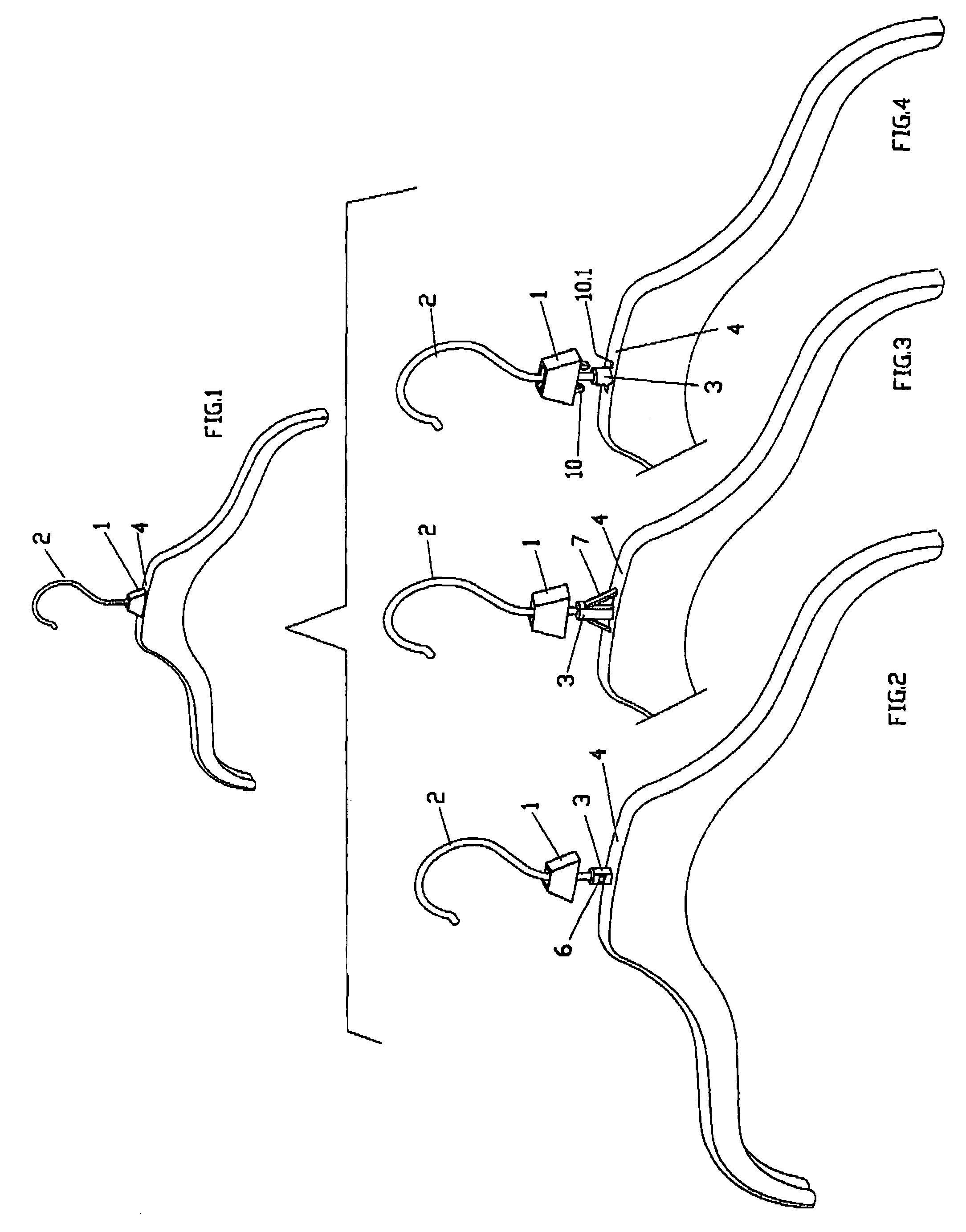
[0062]Referring to FIGS. 13 and 14, wherein like reference characters indicate like parts as above, in a third embodiment, the crown sizer 1 has a pair of oppositely disposed protrusions 9, each of which is disposed in depending relation to project from the peripheral wall to engage in the body 4 of the hanger. Each protrusion 9 is flexible and carries an integral tang 10 at the lower end that extends beyond the plane of the peripheral wall of the sizer 1.
[0063]Referring to FIG. 15, the hanger has a pair of seats 10.1 cut in the body 4 on opposite sides of the post 3 and the protrusions 9 of the sizer 1 are engaged in the respective seats 10.1. As above, each tang 10 is in the form of a tooth with a sloped surface that allows the tang 10 to slide through a seat 10.1 which is in the form of an opening while flexing outwardly until snapping under the seat. At that time, a flat shoulder on the tang 10 fits under the seat 10.1 as shown in FIG. 15 to lock the sizer 1 in place in the hang...
fourth embodiment
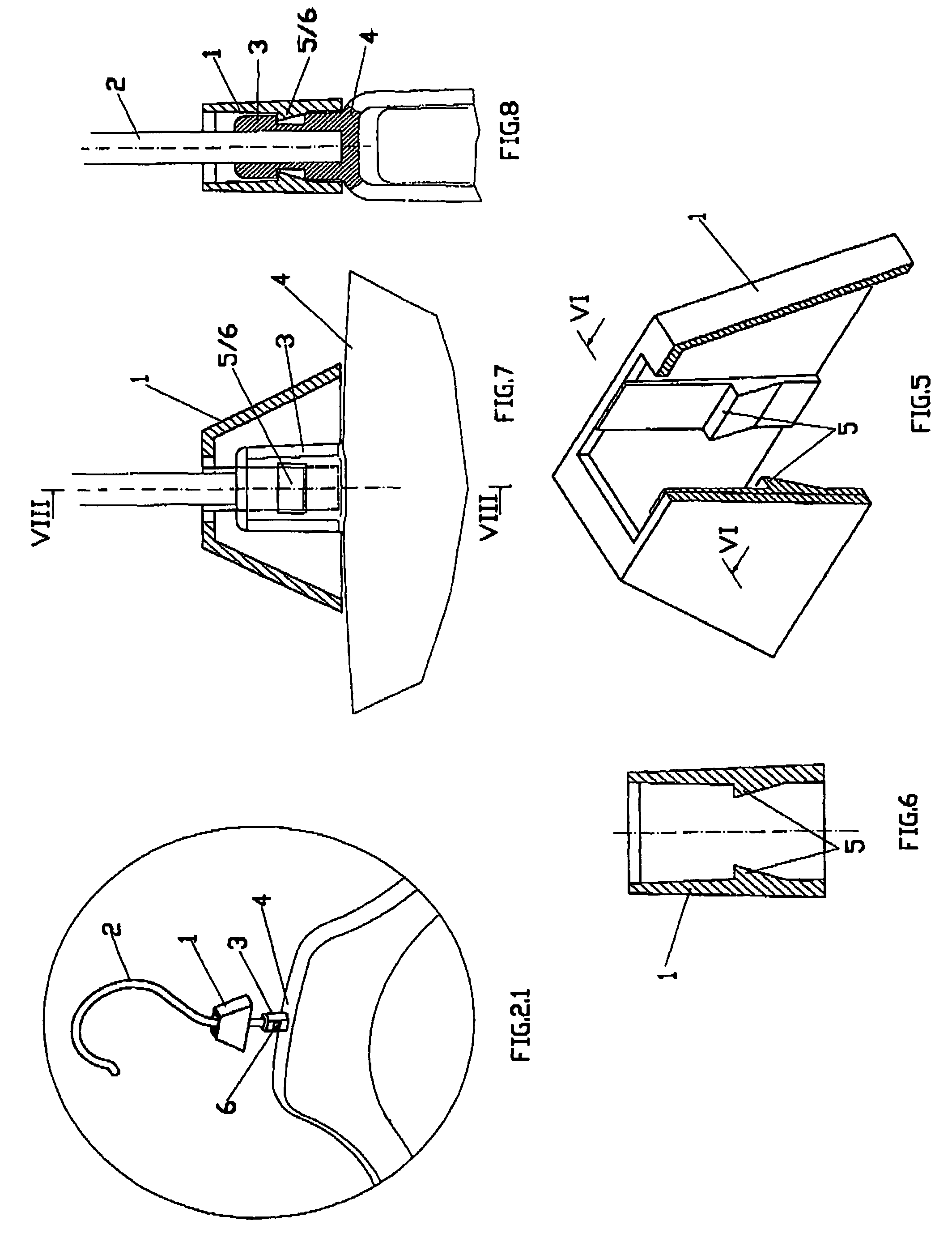
[0064]Referring to FIGS. 16 to 18, wherein like reference characters indicate like parts as above, in a fourth embodiment, the crown sizer 1 is provided with a pair of oppositely disposed protrusions 5 at the upper end of the peripheral wall to engage in the post 3 of a hanger. In addition, the sizer 1 has a pair of oppositely disposed fins 11 that project inwardly from the upper end of said wall to close the open top and a pair of recesses 12 on opposite sides of each fin 11 to render each fin 11 flexible relative to the wall. These recesses 12, which separate the fins 11 from the rest of the encasing structure, make the structure more flexible and thus easier to insert and position the crown sizer 1 on the post 3. As shown, each fin 11 is disposed in a plane perpendicular to a plane of a respective protrusion 5.
[0065]Referring to FIGS. 19 and 20, the post 3 of the hanger is provided with slots 6 on opposite sides to accommodate the protrusions 5.
[0066]As shown in FIG. 20, the prot...
fifth embodiment
[0072]Referring to FIGS. 21 to 23, wherein like reference characters indicate like parts as above, in a fifth embodiment, the crown sizer 1 is provided only with a pair of oppositely disposed fins 11 and a pair of recesses 12 as above at the upper end.
[0073]Referring to FIG. 24, the crown sizer 1 cooperates with a post 3 having slots 15 on opposite sides that receive the fins 11 in interlocking relation to secure the sizer 1 to the post 3. Specifically, as can be seen in FIG. 24, the slots 15 are positioned in front of the fins 11 and are arranged rotated by 90° in relation to the slots 6 described previously (See FIG. 19)
[0074]In this embodiment, in order to simplify the insertion of the crown sizer 1 on the post 3, the upper portion 3.2 of post 3 is provided with sloping surfaces 16 on which the ends of the fins 11 are engaged to slide before they are fitted in the corresponding slots 15.
[0075]Referring to FIGS. 27 to 29, wherein like reference characters indicate like parts as ab...
PUM
 Abstract
Description
Claims
Application Information
 - R&D Engineer
- R&D Manager
- IP Professional
- Industry Leading Data Capabilities
- Powerful AI technology
- Patent DNA Extraction
Browse by: Latest US Patents, China's latest patents, Technical Efficacy Thesaurus, Application Domain, Technology Topic, Popular Technical Reports.
© 2024 PatSnap. All rights reserved.Legal|Privacy policy|Modern Slavery Act Transparency Statement|Sitemap|About US| Contact US: help@patsnap.com


