Power receptacle device with rotatable sockets
- Summary
- Abstract
- Description
- Claims
- Application Information
AI Technical Summary
Problems solved by technology
Method used
Image
Examples
first embodiment
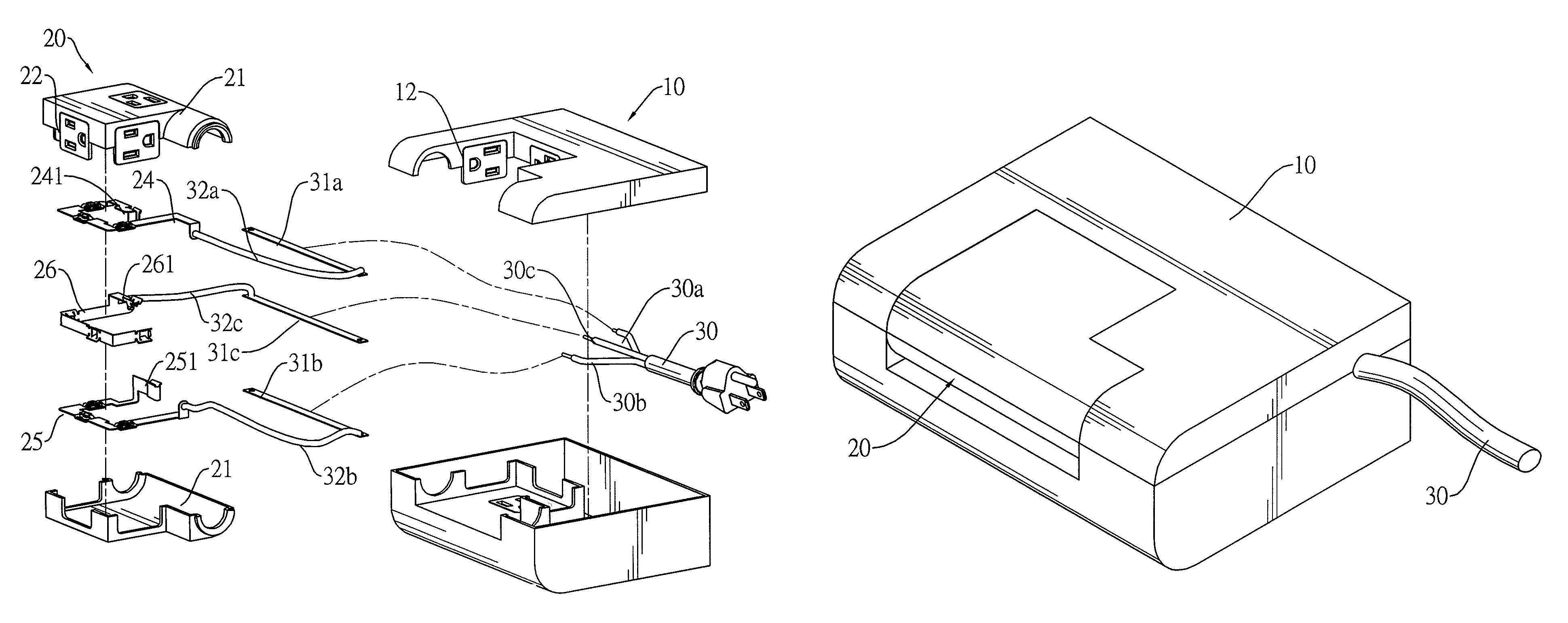
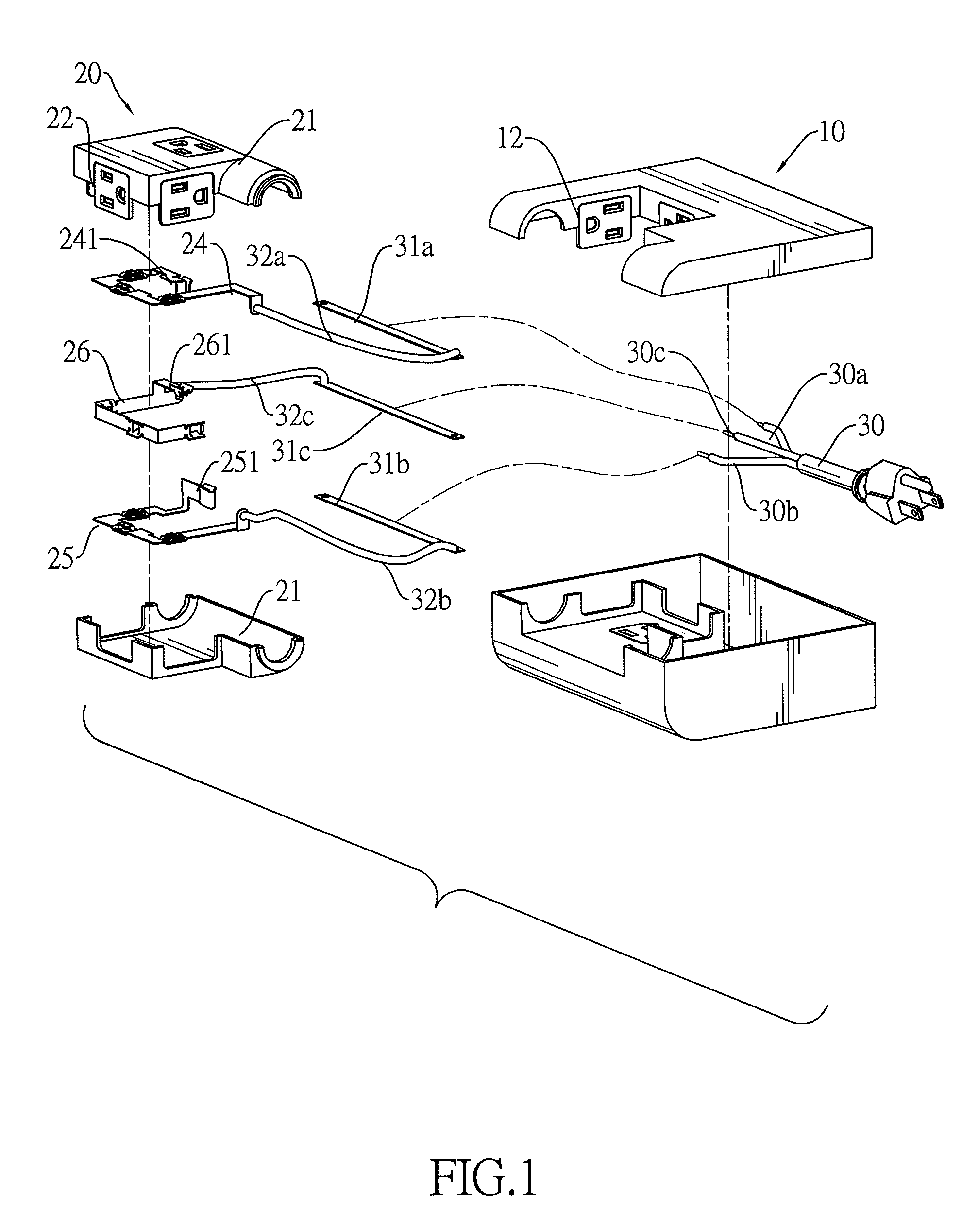
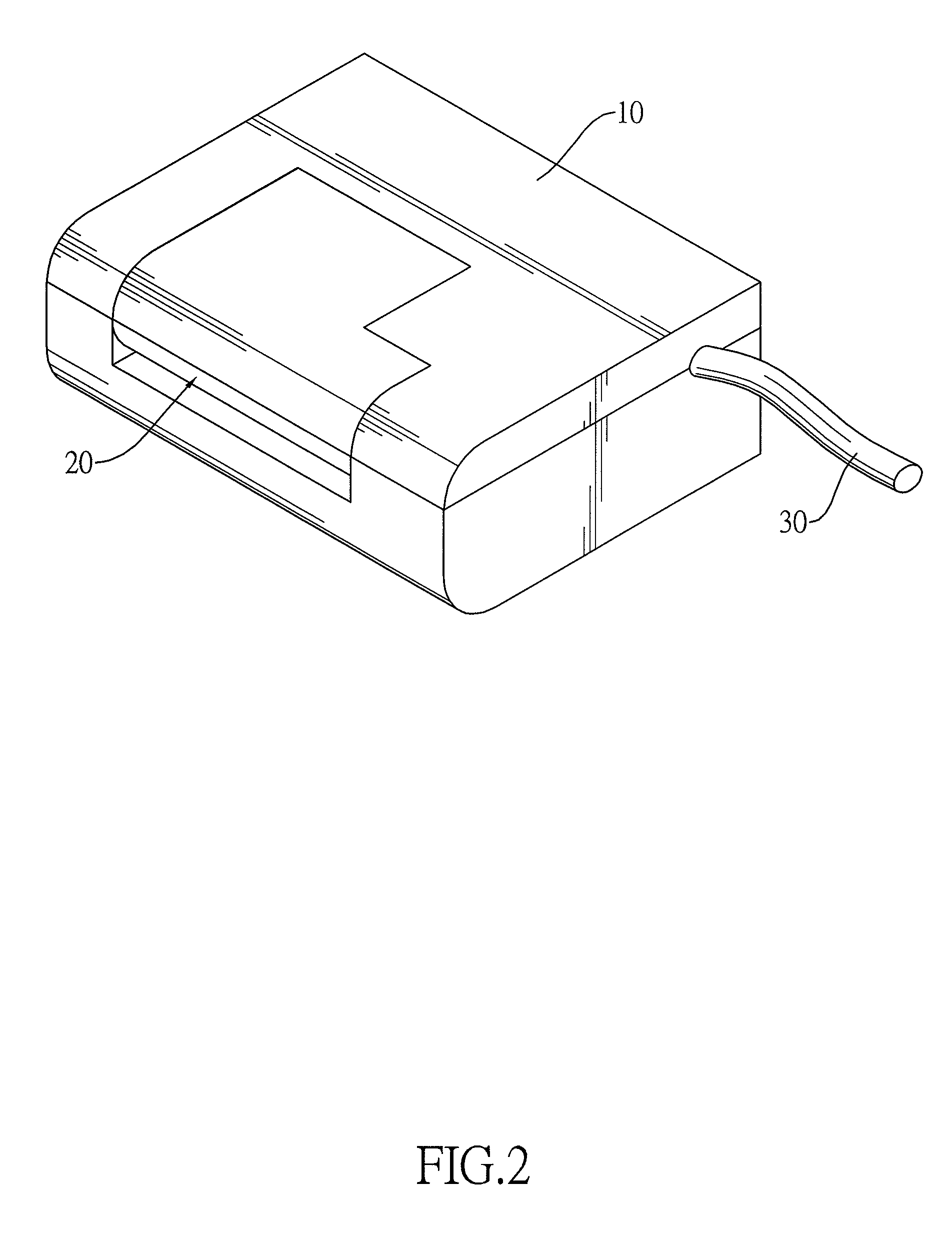
[0024]With reference to FIGS. 1 to 3, a power receptacle device in accordance with the present invention is implemented as a power strip and comprises a stationary base (10) and a rotating base (20).
[0025]The stationary base (10) has one or more sockets (12) and has an electricity connection assembly. The electricity connection assembly can be implemented as a power cable (30) with three cords (30a)(30b)(30c) for transmitting electricity as shown in FIGS. 1 to 12 or implemented as a power plug composed of three contact prongs (40a)(40b)(40c) as shown in FIG. 13. The rotating base (20) is mounted rotatably in the stationary base (10) and has one or more sockets (22). All the sockets (12)(22) in the stationary base (10) and the rotating base (20) are turned toward each other respectively when the rotating base (20) is rotated to a proper position so that the sockets (12)(22) are covered by the rotating base (20). In this embodiment, all the sockets (12)(22) are turned toward each othe...
second embodiment
[0029]With reference to FIGS. 4 and 5, a power receptacle device in accordance with the present invention is implemented as a power strip and comprises a stationary base (10) and two rotating bases (20a)(20b). The stationary base (10) has two notches (13) formed at the same side, and the two rotating bases (20a)(20b) are mounted rotatably and respectively in the notches (13). The stationary base (10) also has a power cable (30). Each of the rotating bases (20a)(20b) has an adjacent surface (23a)(23b) and a socket (22a)(22b) formed on the adjacent surface (23a)(23b) and electrically connected to the power cable (30).
[0030]The sockets (22a)(22b) are covered by the rotating bases (20a)(20b) when the two rotating bases (20a)(20b) are turned to a position where the adjacent surfaces (23a)(23b) of the two rotating bases (20a)(20b) face each other. In this embodiment, as long as the two rotating bases (20a)(20b) turn in the same direction with the same angle, the sockets (22a)(22b) face ea...
third embodiment
[0031]With reference to FIGS. 6 and 7, a power strip in accordance with the present invention comprises a stationary base (10) and two rotating bases (20a)(20b). The stationary base (10) has two opposite edges and two notches (13) formed in the opposite edges. The two rotating bases (20a)(20b) are mounted rotatably and respectively in the notches (13). The stationary base (10) also has a power cable (30). Each of the rotating bases (20a)(20b) has an overlap surface (27a)(27b) and a socket (22a)(22b) formed and on the overlap surface (27a)(27b) and electrically connected to the power cable (30). The sockets (22a)(22b) on the two overlap surfaces (27a)(27b) are covered by the rotating bases (20a)(20b) when the rotating bases (20a)(20b) are turned to overlap each other. As the rotating bases (20a)(20b) rotates outward, the sockets (22a)(22b) in the rotating bases (20a)(20b) are exposed. The electric connection between the power cable (30) and each rotating bases (20a)(20b) may be accom...
PUM
 Abstract
Description
Claims
Application Information
 - R&D Engineer
- R&D Manager
- IP Professional
- Industry Leading Data Capabilities
- Powerful AI technology
- Patent DNA Extraction
Browse by: Latest US Patents, China's latest patents, Technical Efficacy Thesaurus, Application Domain, Technology Topic, Popular Technical Reports.
© 2024 PatSnap. All rights reserved.Legal|Privacy policy|Modern Slavery Act Transparency Statement|Sitemap|About US| Contact US: help@patsnap.com


