
Passive component
a passive component and component technology, applied in the field of passive components, can solve problems such as unwanted peak in the attenuation range, and achieve the effects of improving performance, large attenuation level, and sharp attenuation characteristics
- Summary
- Abstract
- Description
- Claims
- Application Information
AI Technical Summary
Benefits of technology
Problems solved by technology
Method used
Image

Examples
Embodiment Construction
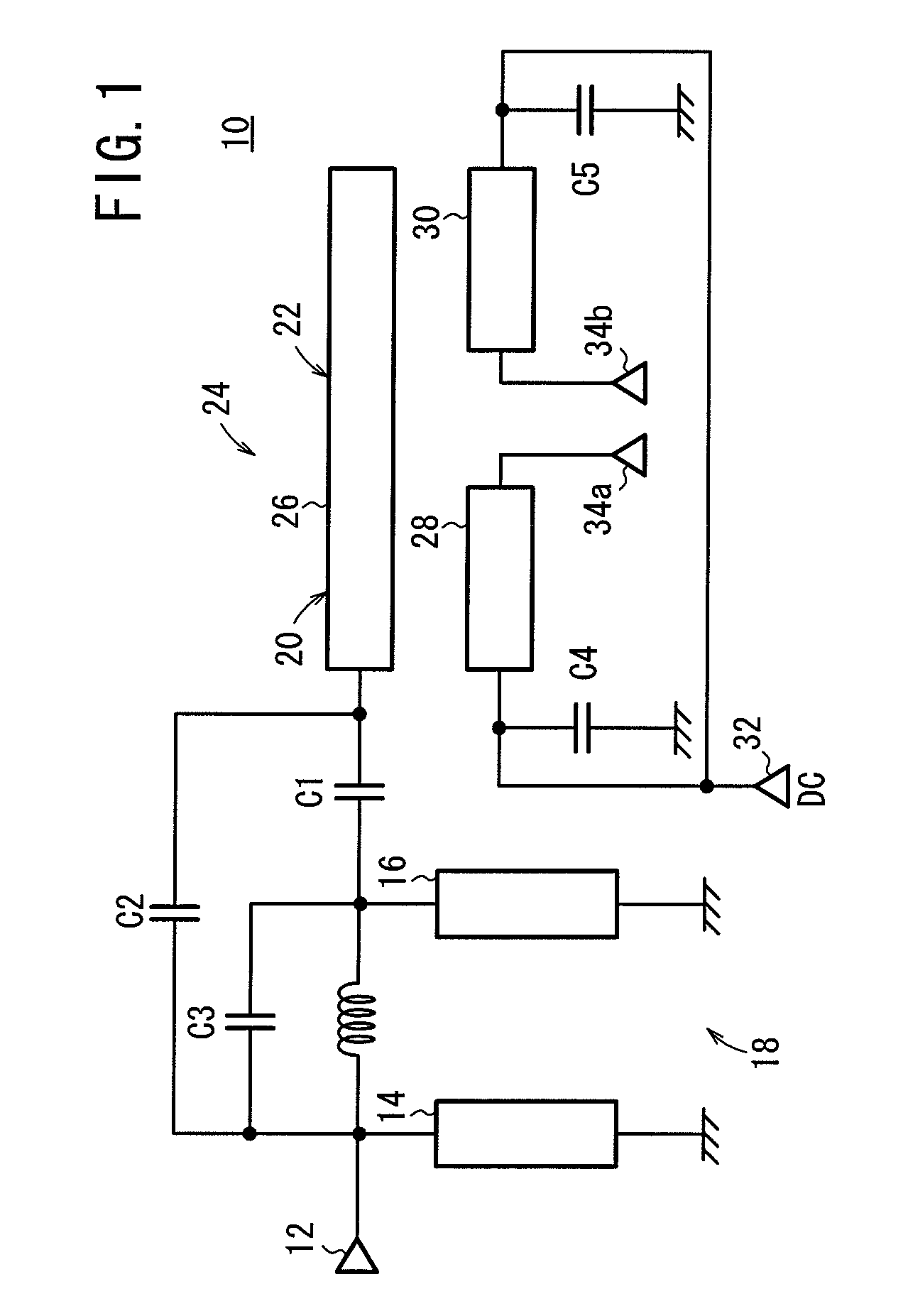
[0038]A passive component according to an embodiment of the present invention shall be described below with reference to FIGS. 1 through 8.
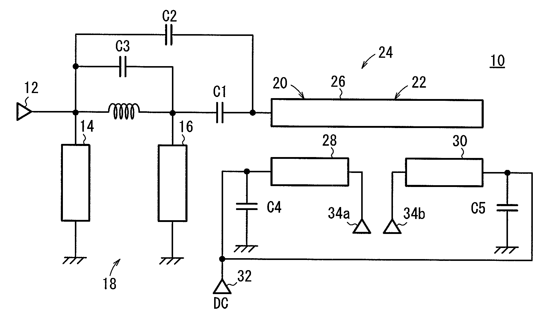
[0039]As shown in FIG. 1, the passive component 10 according to the embodiment comprises a filter 18 according to an unbalanced input / unbalanced output system, having an input resonator 14 connected to an unbalanced input terminal 12, an output resonator 16 coupled to the input resonator 14, and an unbalanced to balanced converter (hereinafter referred to as “converter”) 24 having two coupling dual-lines (a first coupling dual-line 20 and a second coupling dual-line 22).
[0040]The output stage of the filter 18 and the input stage of the converter 24 are connected to each other by a first capacitor C1. The input stage of the filter 18 and the input stage of the converter 24 are connected to each other by a second capacitor C2. The second capacitor C2 functions as a jump capacitor.
[0041]The converter 24 has a first line 26, a second line 28, and a t...
PUM
 Abstract
Description
Claims
Application Information