Display device including function to input information from screen by light

a technology of a display device and a function, which is applied in the direction of user-computer interaction input/output, instruments, computing, etc., can solve the problems of inaccurate identification of the shadow of the object approaching the screen, the difficulty of determining whether or not the object has contacted the screen, and the accuracy of information input drops, so as to achieve accurate determination and enhance the effect of determination accuracy

Active Publication Date: 2010-09-21
JAPAN DISPLAY CENTRAL CO LTD
View PDF12 Cites 48 Cited by
  • Summary
  • Abstract
  • Description
  • Claims
  • Application Information

AI Technical Summary

Benefits of technology

[0016]In this aspect of the present invention, when the object has contacted the screen, spatial changes of a contact portion and a non-contact portion in the imaged image become apparent. Accordingly, by detecting the edges by using the imaged image, a boundary between the contact portion and the non-contact portion is identified, and is utilized in the contact determination, and accuracy of the contact determination is thus enhanced. Moreover, when it is determined that the object has contacted the screen, the position coordinate of the object is calculated by using the detected edges. In such a way, the coordinate position is adapted not to be calculated when the object is not in contact with the screen, and calculation accuracy of the position coordinate is thus enhanced.
[0018]In this aspect of the present invention, a temporal change occurs in the imaged image when the object has contacted the screen, and accordingly, the difference image formed by taking the difference between the multi-gradation image in the current frame and the multi-gradation image in the past frame is obtained. In such a way, the boundary between the contact portion and the non-contact portion is identified based on the temporal change of the imaged image, and is utilized for the contact determination. In such a way, the accuracy of the contact determination is enhanced.
[0020]In this aspect of the present invention, the edge image is suitable for the contact determination / coordinate calculation under a light environment, and the difference image is suitable for the contact determination / coordinate calculation under a dark environment. Meanwhile, it is possible to determine lightness of environmental light based on the gradation value of the multi-gradation image. Accordingly, based on the multi-gradation image, it is determined whether or not the object has contacted the screen by using at least one of the edge image and the difference image, thus making it possible to perform the contact determination in response to the environment. In such a way, the accuracy is further enhanced. Moreover, the position coordinate of the object is calculated by using at least one of the edge image and the difference image, thus making it possible to perform the coordinate calculation in response to the environment. In such a way, the accuracy is further enhanced.
[0022]In this aspect of the present invention, by the counting circuit, the inter-frame difference processing circuit, and the edge detection circuit, the signals indicating the switch having a high possibility to be contacted by the object are outputted by techniques different from one another. Then, by the contact probability calculation circuit, the contact probability is calculated for each switch. Thus, it is made possible to provide a highly reliable contact probability. Accordingly, highly accurate and flexible contact determination and coordinate calculation in response to reliability required for the system are made possible.
[0024]In this aspect of the present invention, the drive condition of the optical sensors is changed based on the output values of the optical sensors, which are varied in response to the external light, thus making it possible to appropriately control sensitivities of the optical sensors.
[0026]In this aspect of the present invention, the multi-gradation data of each of the pixels, which corresponds to the intensity of the light received by the optical sensor elements, is used for the binary determination for reflected light from the object on the display screen and other light, thus making it possible to set a threshold value for performing accurate determination. In such a way, the determination accuracy can be enhanced.

Problems solved by technology

However, the conventional display device including the light input function has a problem that it is difficult to determine whether or not the object such as the finger and the light pen has contacted the screen, and to calculate a coordinate position of the object accurately.
In particular, in a technique of utilizing the shadow made by the object, when an ambient environment is dark, the shadow made by the object approaching the screen cannot be identified accurately.
Moreover, also when the ambient environment is too light, the accuracy in the information input drops.
Moreover, the imaged image obtained by inputting the light is an image of a binary monochrome gradation, and accordingly, there are limitations on determination accuracy in the case of determining reflected light from the object on the screen and other light in a binary manner.

Method used


Image

  • Display device including function to input information from screen by light
  • Display device including function to input information from screen by light
  • Display device including function to input information from screen by light

Examples


first embodiment

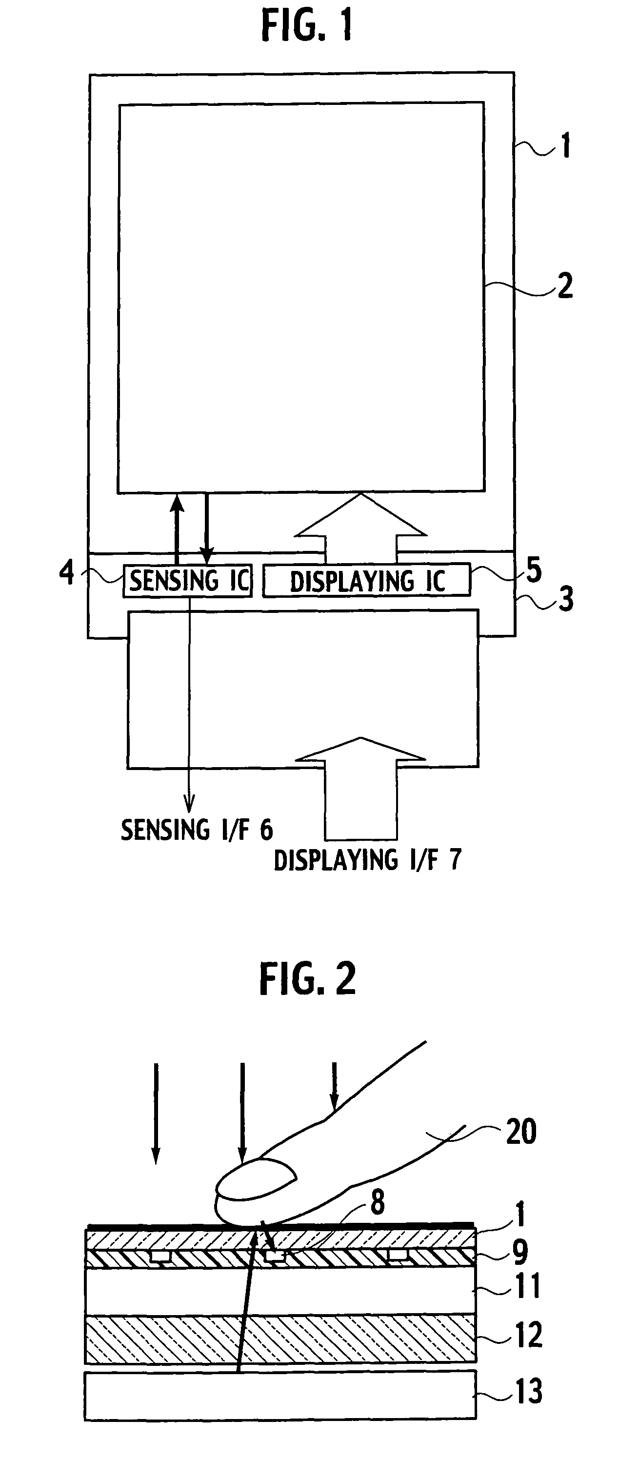
[0113]FIG. 1 is a plan view showing a configuration of a display device in this embodiment. The display device in this drawing includes a display unit 2 formed on an array substrate 1 made of glass, a flexible substrate 3, a sensing integrated circuit (IC) 4 and a displaying IC 5, both of which are formed on the flexible substrate 3, an interface (I / F) 6 for the sensing IC 4, and an interface 7 for the displaying IC.

[0114]In the display unit 2, plural signal lines and plural scan lines are wired so as to intersect each other, and pixels are provided on the respective intersections. The display unit 2 includes a display function to display an image based on a video signal transmitted from a host-side CPU through the displaying interface 7 and the displaying IC 5, a light input function to image an image of an external object approaching a screen, and a function to transmit the imaged image to a host through the sensing IC 4 and the sensing interface 6. The sensing IC 4 performs proce...

second embodiment

[0142]In this embodiment, only a configuration of the sensing IC is different from that in the first embodiment, and a basic configuration of the display device is similar to that in the first embodiment. Accordingly, only the sensing IC is described here. A duplicate description of other portions similar to those of the first embodiment is omitted.

[0143]FIG. 10 is a circuit block diagram showing a configuration of a data processing unit in the sensing IC of this embodiment. The data processing unit in this drawing includes a modulation circuit 81, an inter-frame difference processing circuit 82, a memory 83, an edge detection circuit 84, a contact determination circuit 85, and a coordinate calculation circuit 86. Note that the second embodiment is similar to the first embodiment in that the sensing IC includes the level shifter 61 and the DAC 64 as well as the data processing unit.

[0144]The modulation circuit 81 converts the binary image transmitted from the comparator 41 described...

third embodiment

[0171]Also in this embodiment, only a configuration of the sensing IC is different from that in the first embodiment, and a basic configuration of the display device is similar to that in the first embodiment. Accordingly, only the sensing IC is described here, and a duplicate description of other portions similar to those of the first embodiment is omitted.

[0172]In the display device of this embodiment, as shown in FIG. 35, it is assumed that first to twelfth switches are displayed on the screen and that it is determined which of the switches a finger 20 has touched.

[0173]FIG. 36 is a circuit block diagram showing a configuration of a sensing IC 90 in this embodiment. The sensing IC 90 in this drawing includes a level shifter 91, a modulation circuit 92, a calibration circuit 93, a digital analog converter (DAC) 94, a counting circuit 95, an inter-frame difference processing circuit 96, an edge detection circuit 97, a contact probability calculation circuit 98, and a random access ...


PUM


Abstract

In order to enhance accuracy of determination as to whether an object has contacted a screen and to enhance accuracy of calculation of a coordinate position of the object, edges of an imaged image are detected by an edge detection circuit 76, and by using the edges, it is determined by a contact determination circuit 77 whether or not the object has contacted the screen. Moreover, in order to appropriately control sensitivity of optical sensors in response to external light, by a calibration circuit 93, a drive condition of the optical sensors is changed based on output values of the optical sensors, which are varied in response to the external light.

Description

CROSS-REFERENCE TO RELATED APPLICATIONS[0001]This application is based upon and claims the benefit of priority from Japanese Patent Applications No. 2005-28178 filed on 3 Feb. 2005, No. 2005-55997 filed on 1 Mar. 2005, and No. 2005-188744 filed on 28 Jun. 2005; the entire contents of which are incorporated herein by reference.BACKGROUND OF THE INVENTION[0002]1. Field of the Invention[0003]The present invention relates to a display device capable of inputting information from a screen by light.[0004]2. Description of the Related Art[0005]In recent years, a liquid crystal display device has been widely used for various instruments such as a cellular phone and a notebook computer. The liquid crystal display device includes a display unit having pixels on respective intersections of plural scan lines and plural signal lines, which are wired so as to intersect each other, a drive circuit which drives the scan lines, and a drive circuit which drives the signal lines. Each of the pixels in...

Claims


Application Information

Patent Timeline
Patent Type & Authority Patents(United States)
IPC IPC(8): G09G5/00
CPCG06F3/0412G06F3/042G06F3/03G09G3/20
Inventor NAKAMURA, TAKASHIIMAI, TAKAYUKIYOSHIDA, MASAHIROISHIKAWA, MIYUKIHAYASHI, HIROTAKAKANUMA, TOSHINORI
Owner JAPAN DISPLAY CENTRAL CO LTD
Why Eureka
Try Eureka