Dome pump

a dome pump and pump body technology, applied in the field of pumps, can solve the problems of inconvenient change of components, inability to meet the needs of pump performance, and existing domes that require a relatively large amount of force to collapse the dome,

Active Publication Date: 2010-10-05
KANFER JOSEPH S
View PDF22 Cites 71 Cited by
  • Summary
  • Abstract
  • Description
  • Claims
  • Application Information

AI Technical Summary

Benefits of technology

[0010]In light of the foregoing, it is an object of the present invention to provide an improved dome pump.

Problems solved by technology

These inconsistencies affect pump performance by creating dead spaces, where fluid is trapped behind the collapsed portion of the dome and cannot escape through the outlet.
In similar fashion, existing domes require a relatively large amount of force to collapse the dome.
Most times, however, compromises in performance are accepted over changing these components.
Further considering the issue of pump efficiency, another source of inefficiency is the currently used “floating” ball inlet check valve.
The floating ball design has additional disadvantages in that since it rests in an open position, the floating ball is prone to sticking after it rests for a period of time.
Moreover, in terms of manufacture the floating ball design adds complexity to the pump assembly in terms of adding a component, namely the ball, providing inlet geometry that holds the ball in place, and, in assembly by adding the step of inserting the ball within the inlet.

Method used


Image

  • Dome pump
  • Dome pump
  • Dome pump

Examples


Embodiment Construction

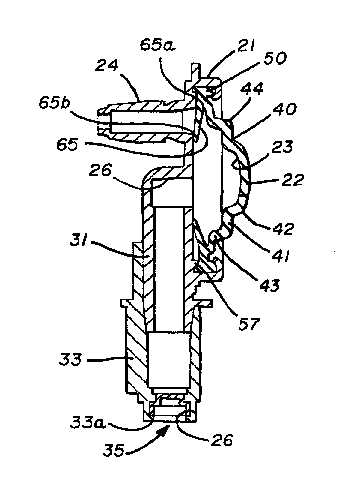
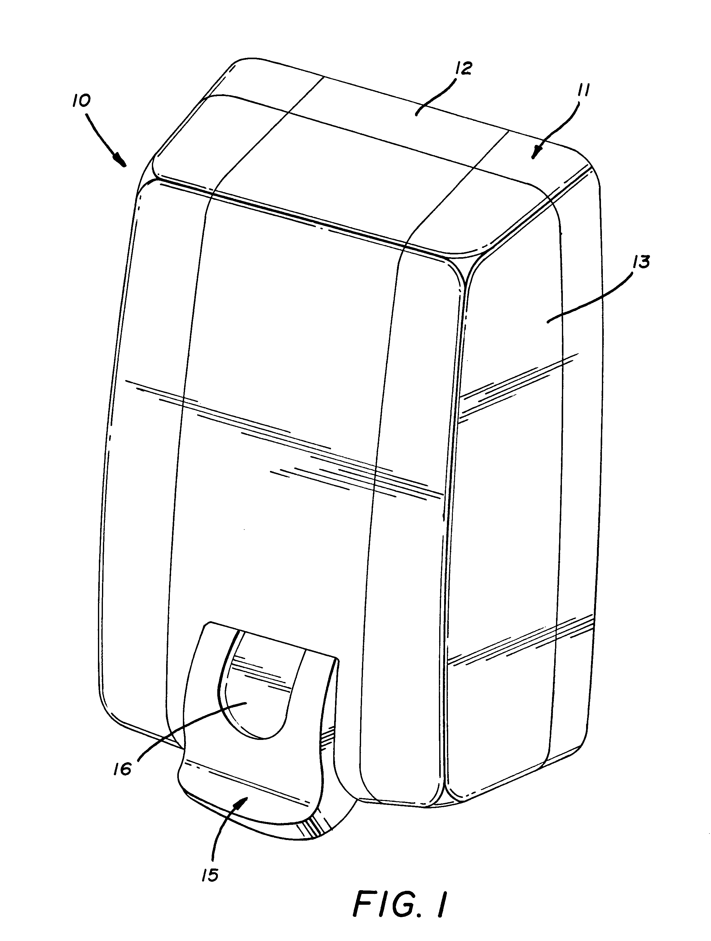
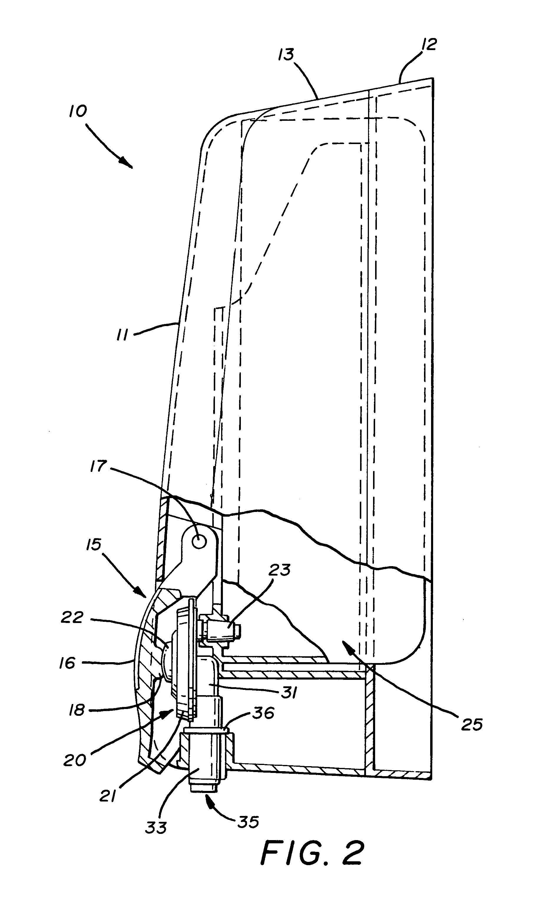
[0025]A dispenser having a pump assembly according to the concepts of the present invention is depicted in FIGS. 1 and 2 and generally indicated by the numeral 10. The dispenser 10 may be any of a number of dispensers available in the art and thus only a general description of its components will be made. The dispenser 10 includes a housing 11 having a base 12 and a cover 13. The cover 13 is typically removable from the base and may be hingedly attached to allow repeated opening and closing of the cover 13. A push bar assembly, generally indicated by the numeral 15, may be attached to the cover 13 and is generally located, such that it is engagable with the pump assembly, generally indicated by the numeral 20, and best shown in FIG. 2.

[0026]With continued reference to FIG. 2, it may be seen that the push bar assembly 15 may include a lever 16 pivotally attached to the cover 13 by a pin 17 or similar member. Lever 16 extends downwardly over the pump assembly 20 and may include a rear...


PUM


Abstract

A pump for dispensing soap from a container in a dispenser, the pump including a base, a flexible dome attached to the base defining a chamber therebetween, an inlet and an outlet formed in the base and opening into the chamber, the inlet being in fluid communication with the container, and wherein the dome has a fold line that facilitates collapsing of the dome. The dome may include an inwardly extending flange that selectively closes the inlet.

Description

RELATED PATENT APPLICATIONS[0001]None.TECHNICAL FIELD[0002]In general, the present invention relates to a pump used in a soap dispenser. More particularly, the present invention relates to a diaphragm pump having a flexible dome that is depressed to pump soap from the dispenser. Most particularly, the present invention relates to a diaphragm pump having a dome that includes a fold line that reduces pumping force and provides for more complete discharge of fluid from the pump. The present invention further relates to a dome having an inwardly extending flap that acts as an inlet value.BACKGROUND OF THE INVENTION[0003]Dispensers are widely available for dispensing a variety of flowable materials including creams, lotions, soaps and pastes, all of which will be generally referred to as “soap.” These dispensers incorporate a variety of pumps including diaphragm pumps. In most cases, the diaphragm pump includes a base to which a flexible dome is attached to define a pumping chamber there...

Claims


Application Information

Patent Timeline
Patent Type & Authority Patents(United States)
IPC IPC(8): B65D37/00
CPCA47K5/1208B05B11/1033
Inventor CIAVARELLA, NICK EREYNOLDS, AARON RWILLIS, DANIEL MYEAGER, ROBERT H
Owner KANFER JOSEPH S
Why Eureka
Try Eureka