Corner joint and method for making the same

a technology of corner joints and joints, applied in the field of corner joints, can solve problems such as side member bending

Inactive Publication Date: 2010-10-05
BROCHEZ ALAIN
View PDF52 Cites 19 Cited by
  • Summary
  • Abstract
  • Description
  • Claims
  • Application Information

AI Technical Summary

Benefits of technology

[0012]The above-mentioned supplementary features can be of different nature according to the invention. On the one hand, these features may consist of means provided on the corner piece and / or the side members, which reinforce the corner as a whole. On the other hand, these features may also consist of means provided on the corner piece and / or the side members, which exclude disadvantageous situations, such as for example disadvantageous effects in case of frost. Further, these features may also consist of a suitable adjustment and / or positioning and / or combination of the different components, such as a result of a number of measures taken according to the invention while the corner joint is manufactured.
[0013]The different supplementary features which can be provided to the corner piece itself can be either or not combined in a symbiotic manner.
[0014]According to a major preferred combination, the corner joint is characterised in that it is provided with a corner piece with insert parts which represents at least the following combination of characteristics:
[0015]that the corner piece has a part on at least one of the insert parts and preferably on both insert parts which extends through the attachment channels of the accompanying side member in an oblique manner as of the accompanying locking means up to the opposite wall of the attachment channels in which the corner piece is situated, whereby this part forms a support up to a place which is situated significantly deeper in the attachment channels than the above-mentioned locking means;
[0016]that the insert parts are equipped with inclined parts which are joined together at an angle and which are each connected at their far ends with the above-mentioned accompanying oblique part, such that pressure created in the oblique parts creates a tensile force in the first-mentioned parts;
[0017]that the inclined parts which are joined together at an angle are situated against the inner wall of the attachment channels in which the insert parts are provided; and

Problems solved by technology

The known techniques are disadvantageous in that fatigue in the corner joining piece soon becomes evident in the frame hanging askew and in that the slightest setting occurring after the wedging up also results in a bending of the side members.

Method used


Image

  • Corner joint and method for making the same
  • Corner joint and method for making the same
  • Corner joint and method for making the same

Examples


Embodiment Construction

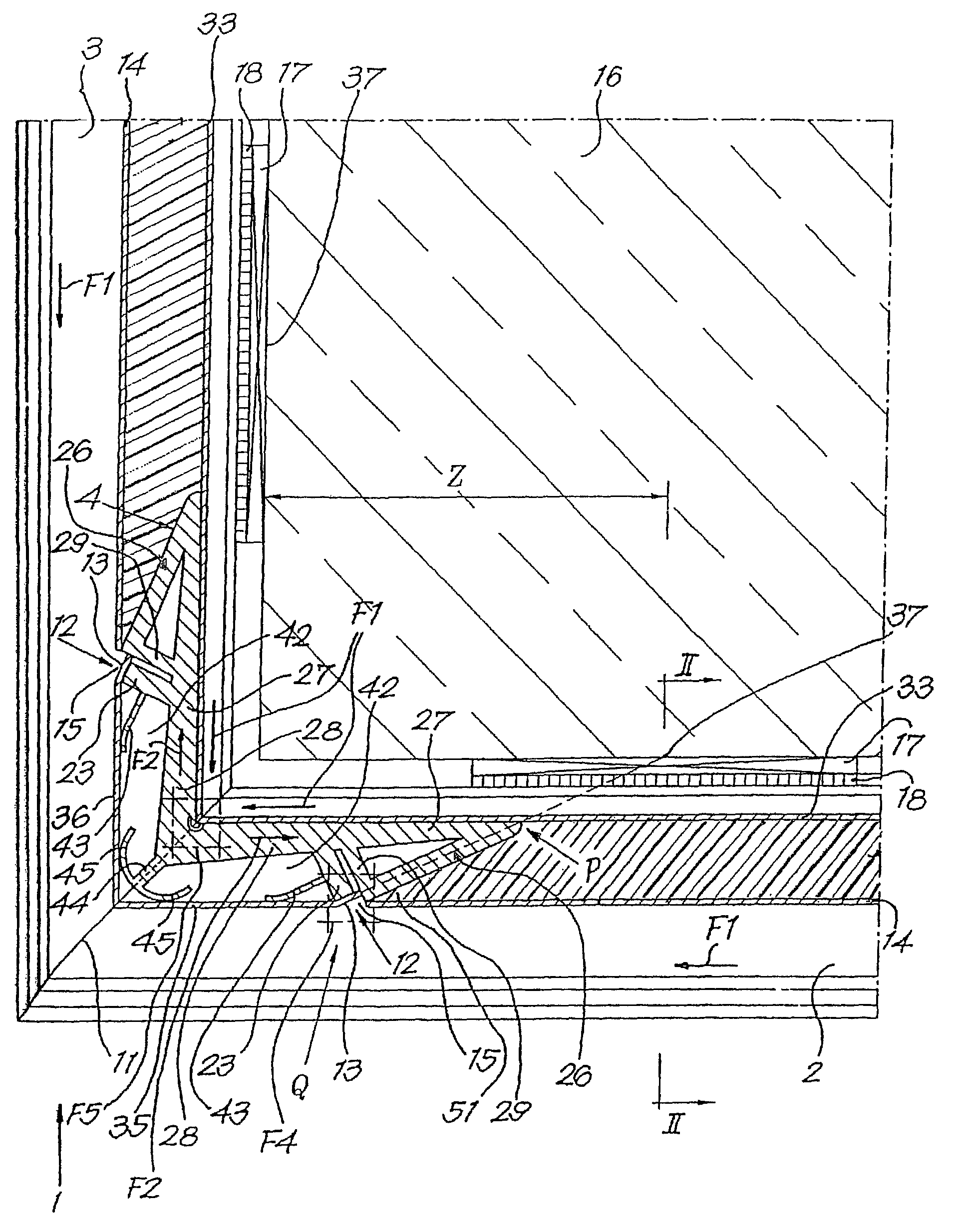
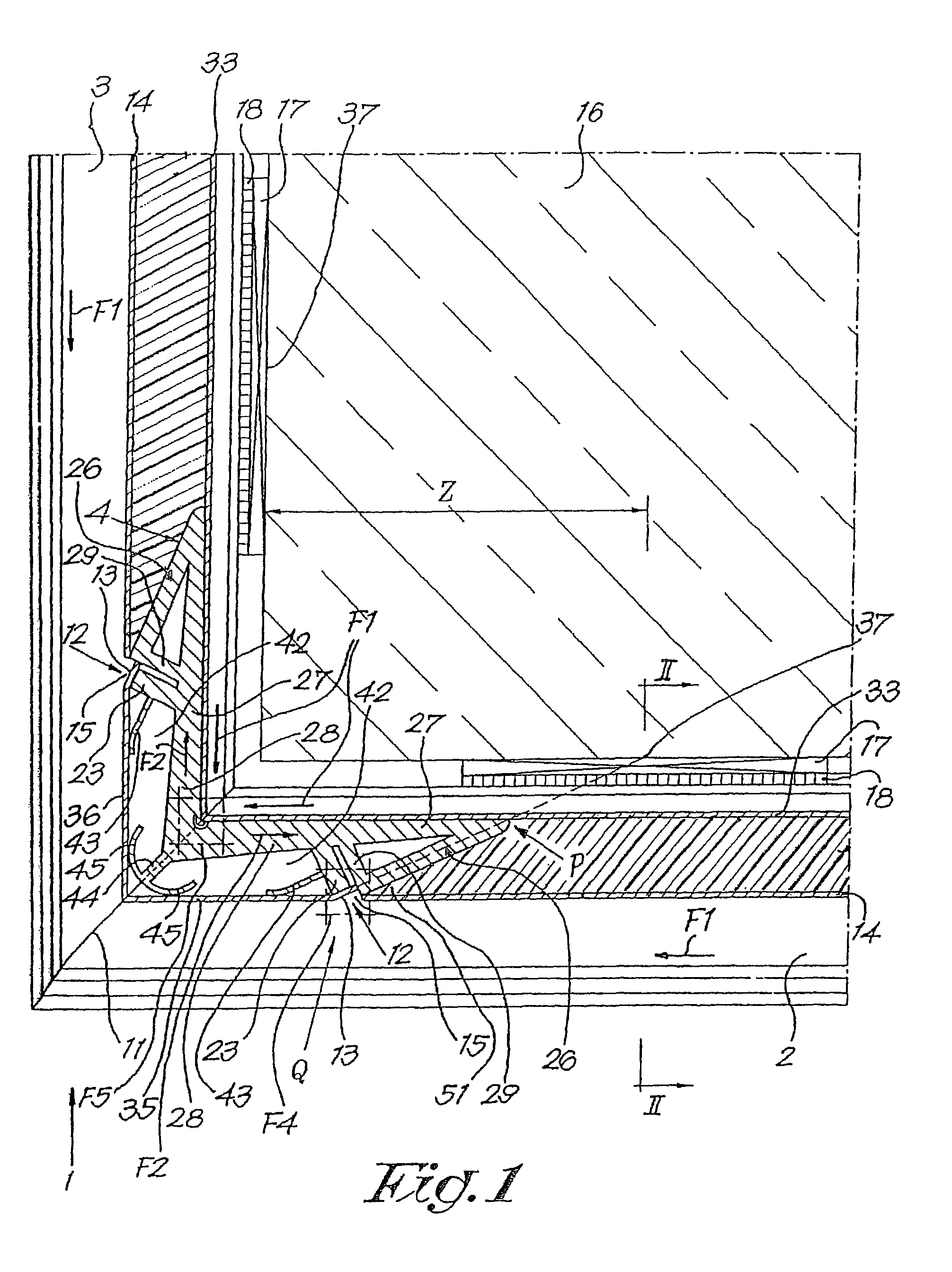
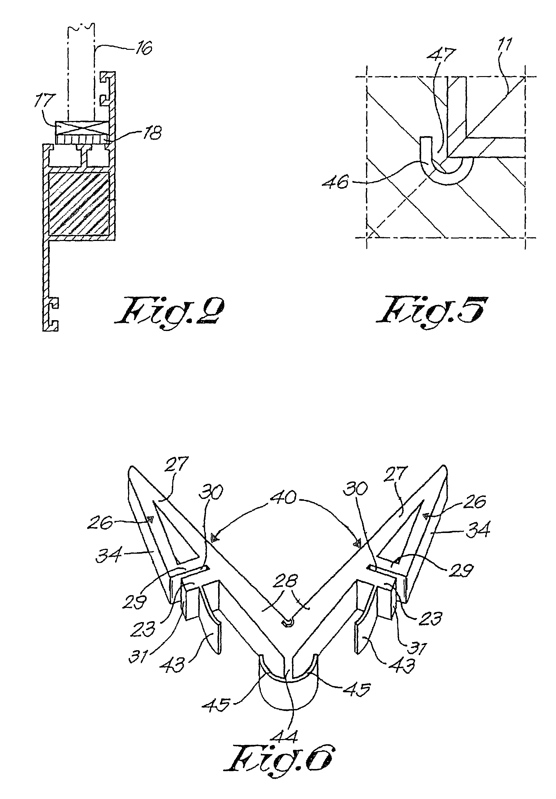
[0031]As represented in FIGS. 1 to 7, the invention concerns a corner joint 1 for connecting hollow side members 2, 3 at a right angle or any other angle whatsoever, whereby the connection is realised by means of a corner piece 4 which is represented more specifically in FIG. 6 and which has two insert parts 5, 6 extending at an angle which are inserted in the respective ends 7, 8 of the side members 2, 3 to be connected, in particular in the attachment channels 9, 10 provided therein.

[0032]These side members 2 and 3 are hereby mitre-sewn in the known manner, and the aim is that, when they are mounted as represented in FIG. 1, they always fit up perfectly on the mitre joint, and under pre-stress according to the invention.

[0033]The mutual interlocking between the corner piece 4 on the one hand and the side members 2, 3 on the other hand is carried out by means of locking means 12 which, in the example from FIGS. 1 to 7, are each time formed of a lip 13 which consists of a pressed-in...


PUM


Abstract

Corner joint, in particular a corner joint (1) for cabinetwork which is made of hollow molds (2-3), whereby this corner joint (1) has at least one infeed corner piece (4) with two infeed parts (5-6) extending at an angle which extend in the respective far ends of the molds (2-3) to be joined, characterized in that it is provided with supplementary features which increase the resistance of this corner joint (1) and thus of the mitre as a whole against deformation.

Description

BACKGROUND OF THE INVENTION[0001]The present invention concerns a corner joint, a method for making such a corner joint and a corner piece to realise such a corner joint in view of a significative inertia reduction of the side members used for making frames.[0002]In particular, it concerns a corner joint for cabinetwork which is made of hollow side members, whereby this corner joint has at least one insert corner piece with two insert parts extending at an angle which extend in the respective far ends of the side members to be joined.[0003]In the first place, the invention is meant for making a corner joint with metal side members, but in a more general way it can also be used, at least to a certain extent, for making corner joints with side members made of other materials, such as PVC and such.[0004]It is known that corner joints in frames, for example of windows and doors, which are made of hollow side members can be realised by mitre-joining the side members and by connecting the...

Claims


Application Information

Patent Timeline
IPC IPC(8): F16B7/00E06B3/976
CPCE06B3/9765Y10T403/555Y10T403/73F16B2200/67
Inventor BROCHEZ, ALAIN
Owner BROCHEZ ALAIN
Why Eureka
Try Eureka