Model railroad coupler
- Summary
- Abstract
- Description
- Claims
- Application Information
AI Technical Summary
Benefits of technology
Problems solved by technology
Method used
Image

Examples
Embodiment Construction
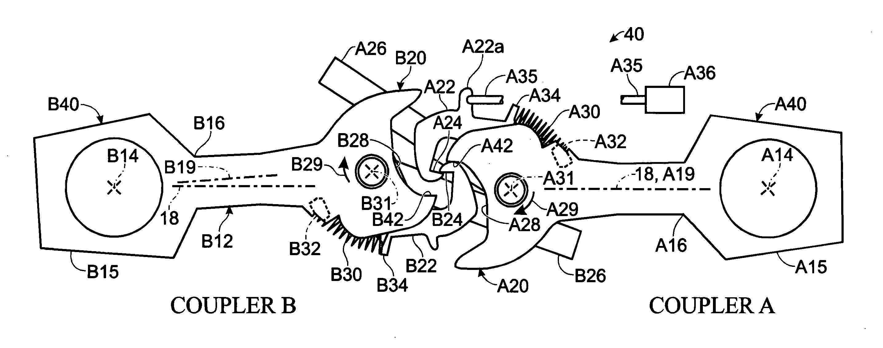
[0017]Referring to the drawing figures, it will be appreciated that the new coupler head and centering mechanism may be used in the same coupler, however, for purposes of clarity, they are not shown in a single drawing figure.
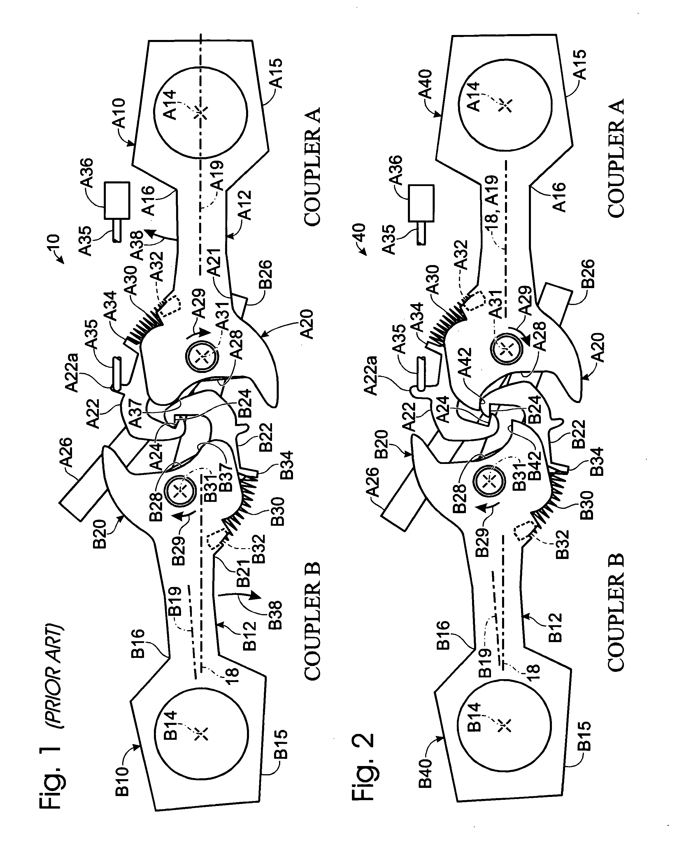
[0018]Referring now to FIG. 1, prior art couplers are depicted generally at 10. Two couplers, coupler A and coupler B are depicted, each having essentially the same elements and like reference numbers. The notation A**, i.e., A10 refers to coupler A and B10 refers to coupler B, is used herein. If an “A” or “B” is not indicated, the reference character refers to both couplers. Coupler A, as described herein, is the “lead” coupler, i.e., attached to a piece of rolling stock which is exerting a pulling force on the “trailing” coupler, i.e., coupler B. In the first portion of this description, the lead coupler is mechanically actuated remotely, e.g., by an actuator carried in the rolling stock to which coupler A is fixed, and which may respond to a remote signal, s...
PUM
 Abstract
Description
Claims
Application Information
 - R&D Engineer
- R&D Manager
- IP Professional
- Industry Leading Data Capabilities
- Powerful AI technology
- Patent DNA Extraction
Browse by: Latest US Patents, China's latest patents, Technical Efficacy Thesaurus, Application Domain, Technology Topic.
© 2024 PatSnap. All rights reserved.Legal|Privacy policy|Modern Slavery Act Transparency Statement|Sitemap