Foldable chair and ladder combination

a folding chair and step ladder technology, applied in the field of furniture, can solve the problems of limited success of combining chairs and ladders into a single piece of furniture, limited height ladders, and uncomfortable chairs,

Inactive Publication Date: 2010-11-09
COLE KIMBERLY J
View PDF41 Cites 9 Cited by
  • Summary
  • Abstract
  • Description
  • Claims
  • Application Information

AI Technical Summary

Benefits of technology

[0009]In an additional embodiment, the assembly includes an upper step or platform assembly having third and fourth platforms pivotally connected to the center leg and to a front support member. Once again, the various components of the upper step or platform assembly are connected in a manner forming a parallelogram linkage such that as the front support member swings or moves outward away from the center leg, the third and fourth platforms also move outward to form additional steps or shelf surfaces. The upper step assembly operates independent of the lower step assembly thereby enabling the apparatus to function as a chair when the upper step assembly is raised or located in line with the center leg and as a ladder when the upper step assembly is lowered such that the third and fourth platforms form additional steps or parallel surfaces.

Problems solved by technology

Over the years, attempts at combining chairs and ladders into a single piece of furniture have met with limited success.
Many of the designs resulted in uncomfortable chairs, limited height ladders, stability concerns and / or cumbersome operability.
Often the designs were overly complicated with limited use.
While both patents illustrate a device capable of converting a chair into a ladder, neither device enables folding the entire assembly for storage.
The device, however, is complicated and includes a plurality of pivotable links interconnecting the various legs and supports all of which must be folded in a precise complicated manner to transform the device between a ladder and a chair.

Method used


Image

  • Foldable chair and ladder combination
  • Foldable chair and ladder combination
  • Foldable chair and ladder combination

Examples


Embodiment Construction

[0020]The following description of the preferred embodiment(s) is merely exemplary in nature and is in no way intended to limit the invention, its application, or uses.

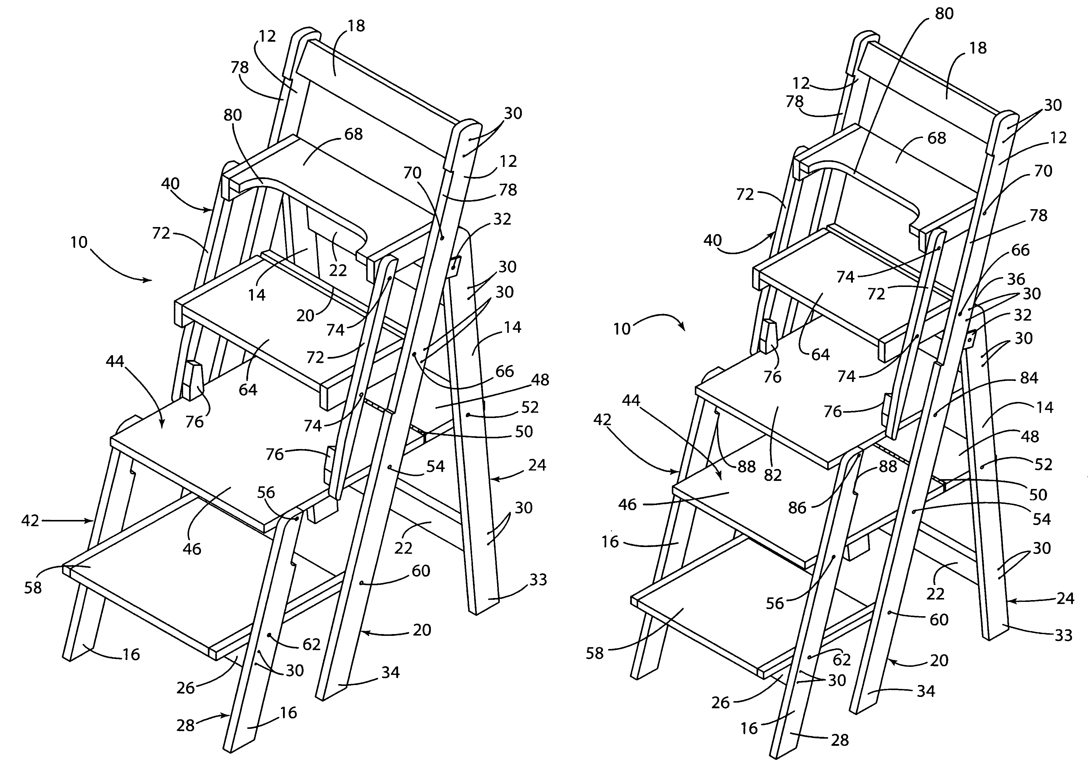
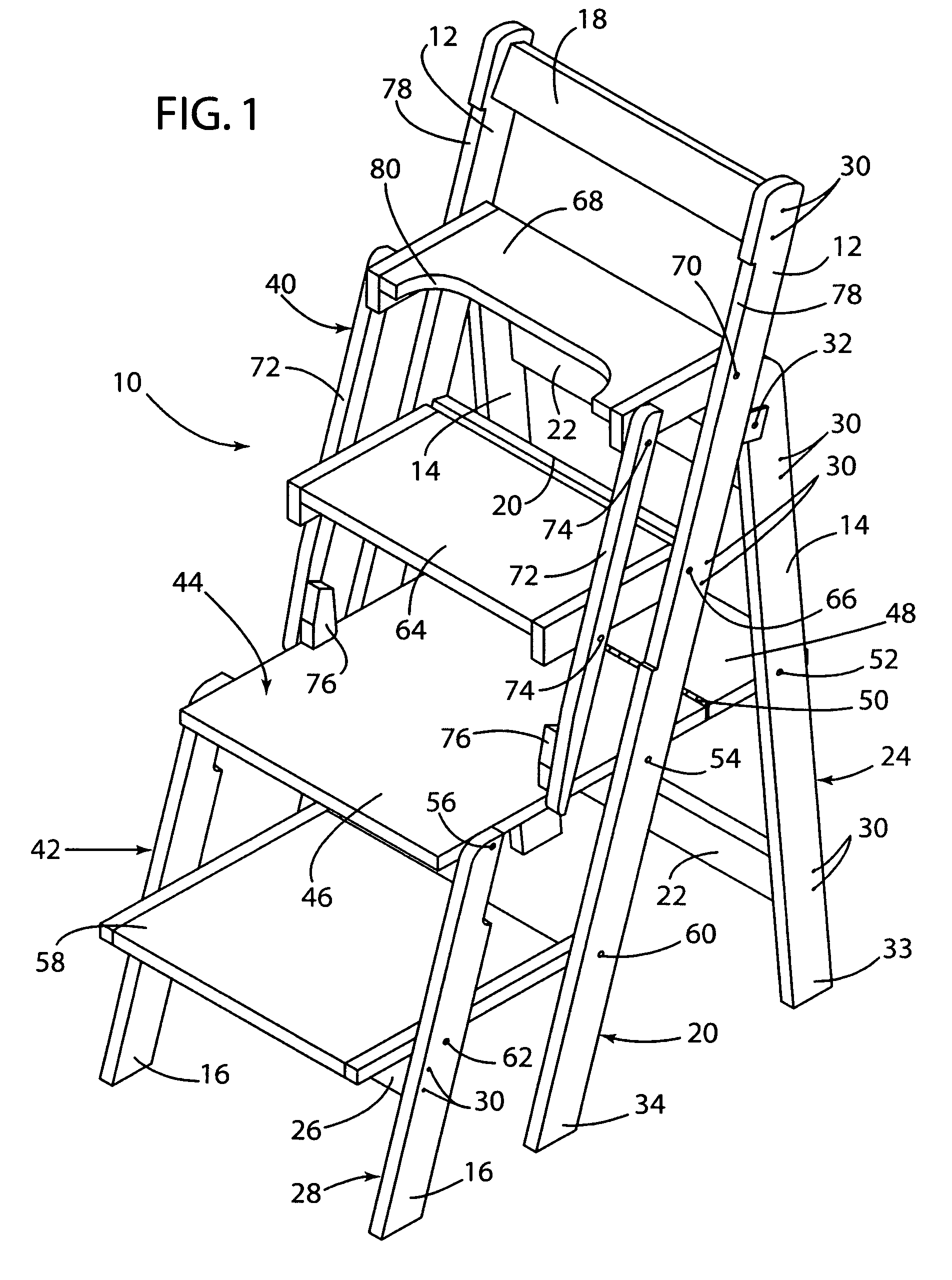
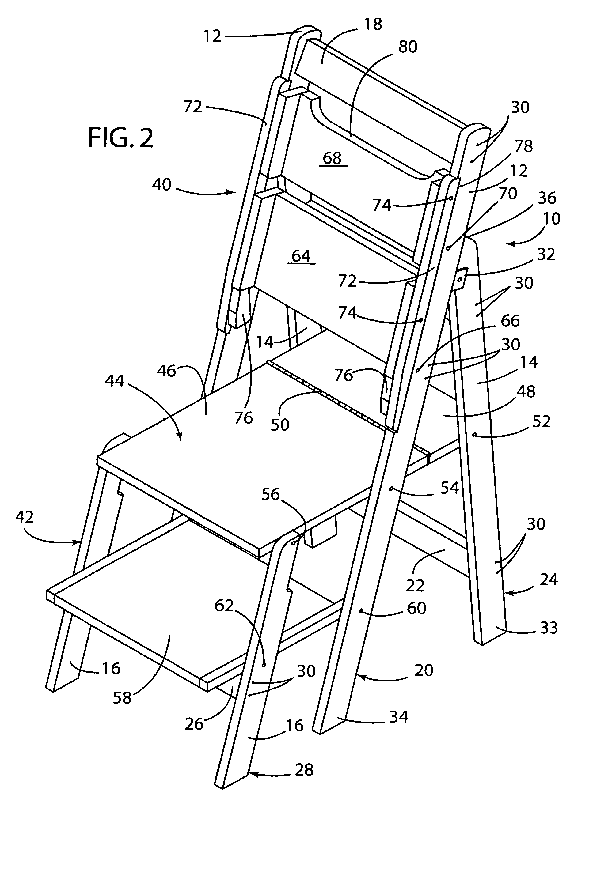
[0021]Referring to the drawings, a combination chair and ladder assembly, seen generally at 10, according to the present invention is shown. As illustrated in FIG. 1 the chair and ladder assembly 10 includes center legs 12, rear legs 14 and front legs 16. Cross members 18 connect the center legs 12 to form a center leg assembly 20. Cross members 22 connect the rear legs 14 to form a rear leg assembly 24. In addition, a cross member 26 connects the front legs 16 to form a front leg assembly 28. As illustrated in the drawings, suitable fasteners 30 extend through the various leg members 12,14,16 to attach the leg members 12, 14, 16 to the cross members 18, 22, 26.

[0022]The rear leg assembly 24 is pivotally connected to the center leg assembly 20 using a bracket and pivot pin 32. Accordingly, the lower end 33 of the rear...


PUM


Abstract

A combination chair and ladder assembly including a center leg, a rear leg and a front leg wherein the rear leg is pivotally connected to the center leg and swings outwardly away from the center leg. The assembly includes a lower step or platform assembly including a first platform having first and second portions with a hinge connecting the first and second portions. The front leg is connected to the first platform. In addition, the chair and ladder assembly may include an upper step or platform assembly having a plurality of platforms pivotally connected to the center leg and to a front support member. The lower step or platform assembly operates independently of the upper step or platform assembly.

Description

CROSS-REFERENCE TO RELATED APPLICATIONS[0001]Not ApplicableBACKGROUND OF THE INVENTION[0002]1. Field of the Invention[0003]The present invention relates to furniture and more particularly to a foldable chair and step ladder combination.[0004]2. Description of Related Art[0005]Over the years, attempts at combining chairs and ladders into a single piece of furniture have met with limited success. Many of the designs resulted in uncomfortable chairs, limited height ladders, stability concerns and / or cumbersome operability. Often the designs were overly complicated with limited use. For example, U.S. Pat. No. 1,950,591 to Bing discloses a chair ladder wherein the front portion of the seat rotates upward and around a front pivot point until it rests on the rear portion of the seat to form a ladder. In addition, U.S. Pat. No. 1,755,680 to Wuest illustrates another variation of a chair ladder wherein the rear legs act as both the back of the chair and as legs of the ladder. Similar to the ...

Claims


Application Information

Patent Timeline
Patent Type & Authority Patents(United States)
IPC IPC(8): A47C13/00
CPCA47C12/02
Inventor COLE, KIMBERLY J.
Owner COLE KIMBERLY J
Why Eureka
Try Eureka