
Clamp for correcting the external ear and method of using the clamp

a technology for correcting the external ear and using a clamp, which is applied in the field of clamps, can solve the problems of keeping the ear in an excessive deformation state, and achieve the effect of quick and effective correction

Inactive Publication Date: 2010-12-14
SORRIBES MICHAEL MIRAVET
View PDF12 Cites 17 Cited by
  • Summary
  • Abstract
  • Description
  • Claims
  • Application Information

AI Technical Summary

Benefits of technology

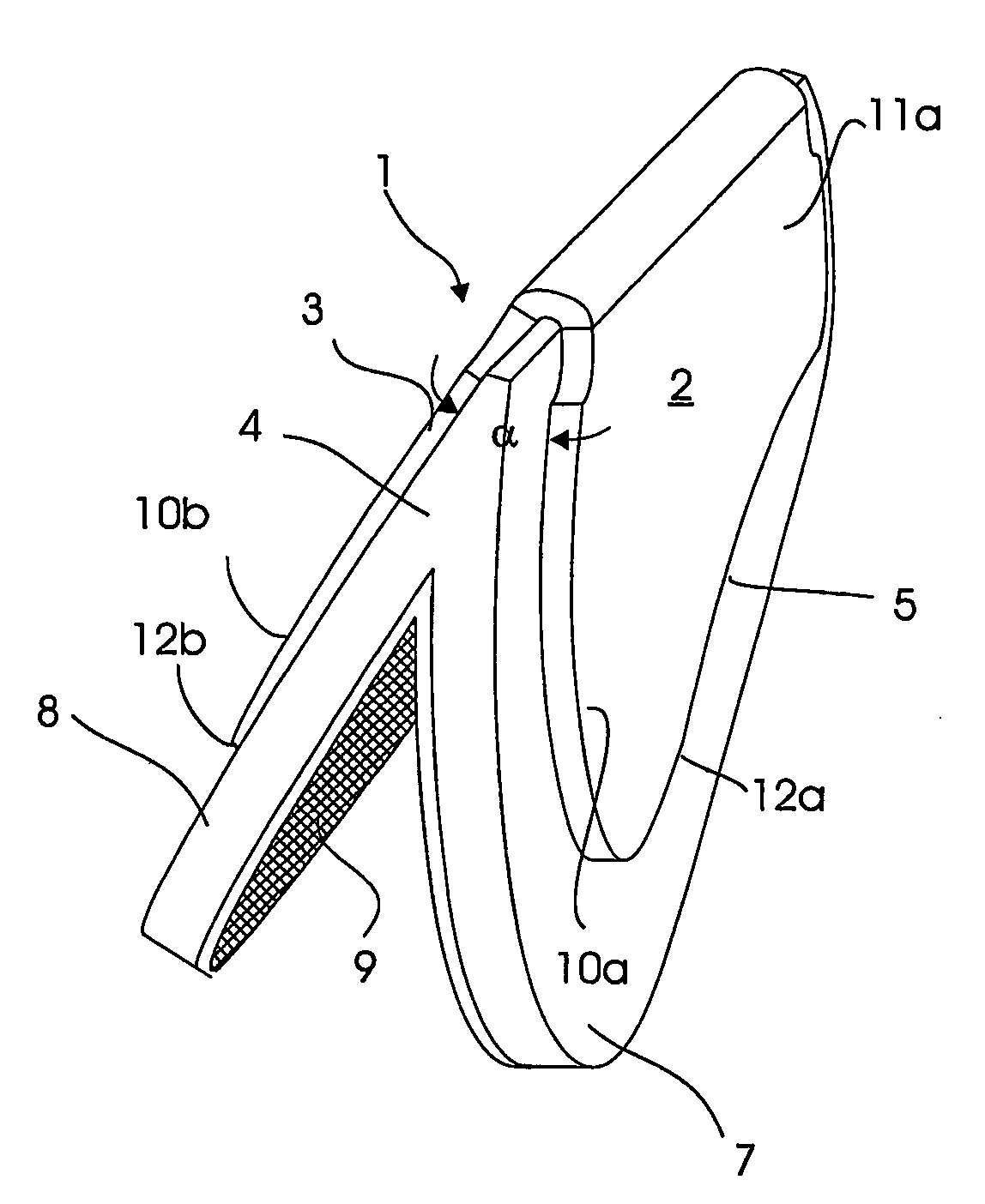
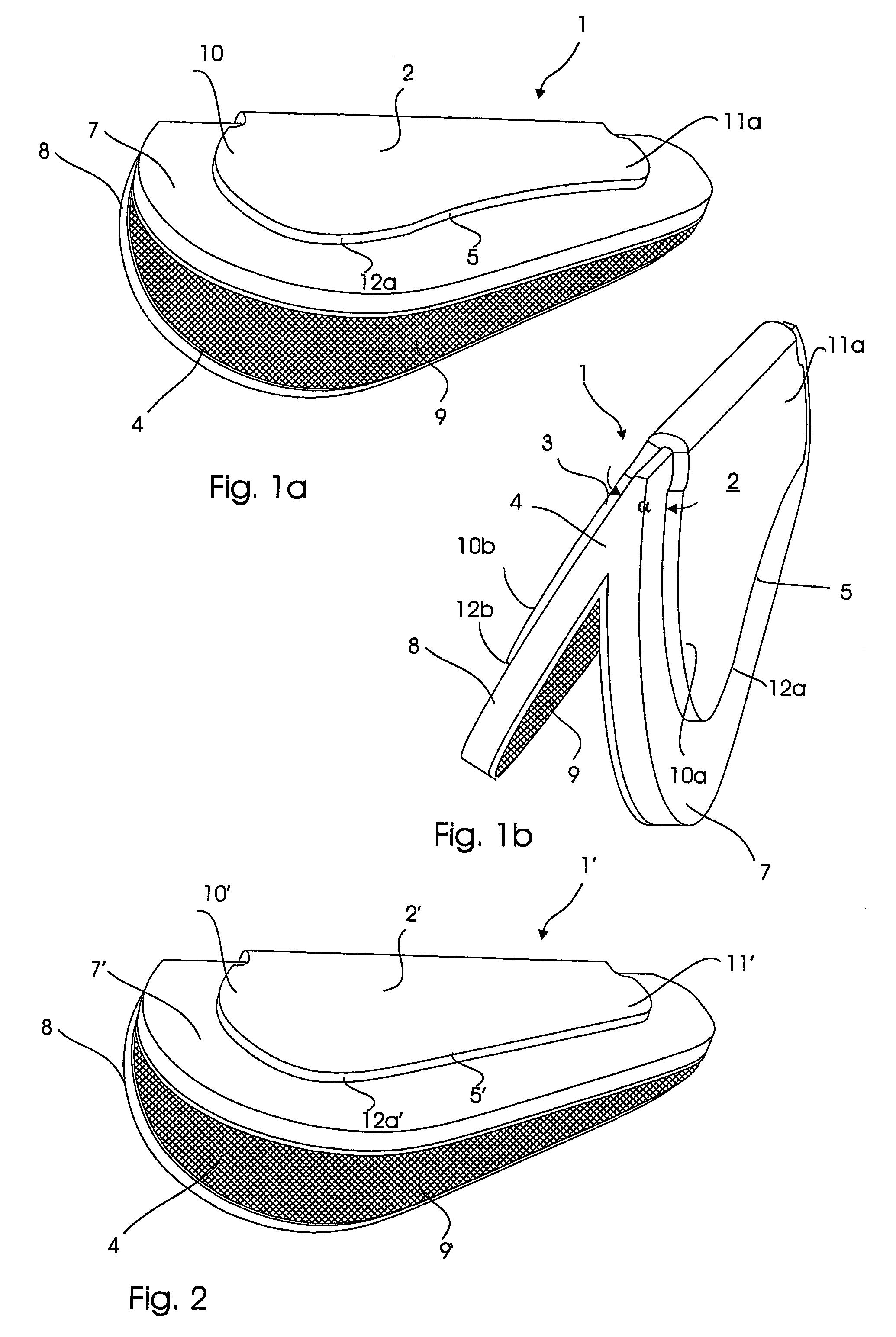
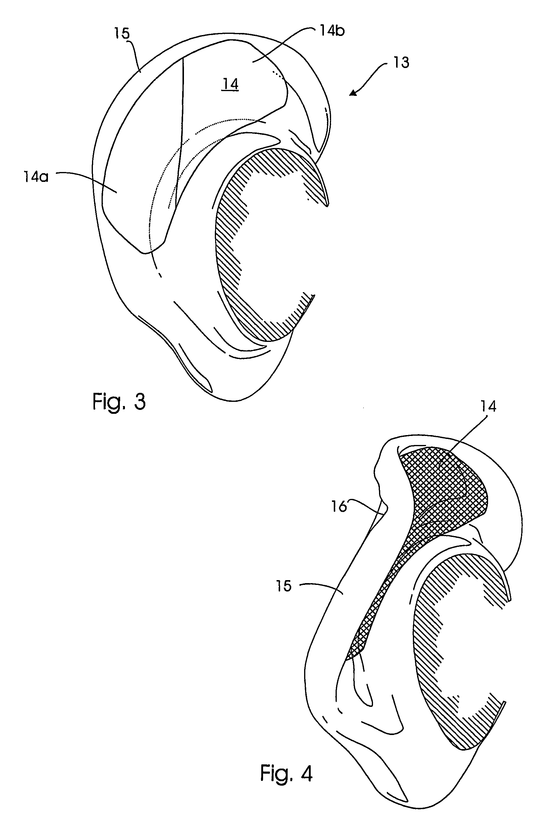
"The present invention provides a device for correcting the shape of an exterior ear by using a U-shaped or V-shaped clamp made of deformable metal. This clamp can keep the ear in a deformed state while exerting a clamping force on a small selected local area of the artificially constructed cartilage fold. The clamp can initiate healing of new cartilaginous scar tissue that fills the created lesion cavities as newly formed cartilaginous tissue advantageously will be formed in form of the cartilage structure of a normal anthelix. The remaining part of the ear fold that constitutes the new anthelix is mainly kept unaffected by the clamp if the two legs of the clamp have a mutual first angle which is smaller than or equal to 90° and, after mounting around the cartilage fold, is mechanically forced in to a second angle which is smaller than or equal to the first angle. This particular U-shape or V-shape will cause two opposite points on the shaped anthelix of the excessively deformed ear to be affected by a deformation force giving the necessary compression, stretching and pulling of the cartilage for this cartilage to be lesioned to heal in normal anthelix form."

Problems solved by technology

A clamp or cramp having such a form can keep the ear in an excessively deformed state, in which the clamping force is only exerted on a small selected local area of the artificially constructed cartilage fold, but on the other hand vertex of the ear fold is stretched and pulled until the elastic cartilage fibers have been gently stretched and given a permanent lesion.

Method used


Image

  • Clamp for correcting the external ear and method of using the clamp
  • Clamp for correcting the external ear and method of using the clamp
  • Clamp for correcting the external ear and method of using the clamp

Examples


Embodiment Construction

[0022]In a preferred embodiment the clamp has a longitudinal extent which mainly corresponds to the length of the anthelix of a normal ear to thereby exert an approximately uniform clamping force from opposite outer sides of the fold in its entire extent. Alternatively a number of smaller, correspondingly shaped clamps can be mounted side by side along the cartilage fold.

[0023]A preferred material for the clamp according to the present invention is metal, as metals are known to be able to maintain their shape after deformation. The legs of a metal clamp extending over a cartilage fold can advantageously be squeezed towards each other until opposite areas along the inner side of the two legs are contacting and squeezing on corresponding edge areas along the outer side of the cartilage fold. The angle between the legs is reduced by e.g. pressing on the outer side of the legs until the clamp has been deformed to the desired extent. The metal maintains the forced deformation, and the co...


PUM


Abstract

A clamp in form of a mainly U-shaped or V-shaped device serves for non-invasively affecting a cartilage fold on for example the exterior ear by a stretching and compressive force. The clamp is shaped as a V, in which the angle α between the legs of the V prior to use is equal to or smaller than 90°, and the angle β between the legs of the V, in use mounted on a cartilage fold, is smaller than the angle α. The clamp is made of a material that can be given a permanent deformation and which therefore is able to maintain a constant pressure on local, opposite areas of the cartilage fold.

Description

CROSS-REFERENCE TO RELATED APPLICATIONS[0001]This application is a continuation of International application PCT / DK2004 / 000620 filed Sep. 17, 2004, the entire content of which is expressly incorporated herein by reference thereto.BACKGROUND ART[0002]The invention relates to a clamp in form of a mainly U-shaped or V-shaped device for non-invasively affecting a cartilage fold on e.g. the exterior ear with stretching and compressive forces.[0003]Kids with jug-ears, i.e. lacking or having weakly developed anthelix and crura of anthelix, are often teased but also grown ups with untreated jug-ears can experience these as a physical handicap.[0004]Surgical procedures for treating jug-ears and similar ear disorders will be known to a person skilled in the art and will not be discussed any further here. However, invasive correction is painful and requires local or general anaesthesia just as it leaves cosmetically disfiguring scars.[0005]From the inventor's own International Patent Applicati...

Claims


Application Information

Patent Timeline
Patent Type & Authority Patents(United States)
IPC IPC(8): A61B17/08A61F11/00
CPCA61F11/00A61F5/05891
Inventor SORRIBES, MICHAEL MIRAVET
Owner SORRIBES MICHAEL MIRAVET
Learn More