Adjustable electrical box hanger bar assembly

a technology of electrical boxes and hangers, which is applied in the direction of machine supports, filing appliances, coupling device connections, etc., can solve the problems of limiting the range of locations where fixtures may be placed, unable to direct joist connections, and the floor covering material or sheathing is not designed to support loads

Active Publication Date: 2010-12-28
THOMAS & BETTS INT INC
View PDF52 Cites 77 Cited by
  • Summary
  • Abstract
  • Description
  • Claims
  • Application Information

AI Technical Summary

Benefits of technology

[0010]The present invention still further provides an adjustable hanger bar assembly securable to a support structure including an elongate first member and an elongate second member having a top wall and spaced sidewalls depending therefrom. The first member is telescopically received along the second member and movable along a longitudinal axis of the second member. A securement section is supported on the second member and has a portion offset from said top wall and sidewalls. The securement member captures the first member within the second member and permits relative movement between the first and second members in a direction along the longitudinal axis of the second member, and restricts motion between the first and second members in a direction transverse to the longitudinal axis.
[0011]The present invention may still further provide an adjustable hanger bar assembly for securing an electrical box to a support structure including an elongate first member having a top wall longitudinally bounded by a pair of opposed sidewalls. An elongate second member has a top wall and spaced sidewalls depending therefrom. The second member receives in slidable engagement the first member, wherein the first member is movable along a longitudinal axis of the second member. The second member includes a first engagement structure offset from the second member top wall and sidewalls. The first member is positionable between the engagement structure and the top and sidewalls of the second member such that relative movement between the first and second members in a direction along the longitudinal axis of the second member is permitted and motion between the first and second members in a direction transverse to the longitudinal axis is restricted.

Problems solved by technology

The ceiling covering material or sheathing is not designed to support loads perpendicular to its surfaces.
To achieve this, a fixture may be secured directly to a joist; however, this limits the range of locations where the fixture may be placed.
Such a limitation is problematic since it is often desirable to place the fixture in a specific position on the ceiling in order to achieve a desired lighting pattern and / or a pleasing aesthetic.
Therefore, if no joist is adjacently positioned to the desired fixture location, direct joist connection is not possible.
However, forming the inwardly turned flanges involves additional manufacturing steps and complicates the construction.

Method used


Image

  • Adjustable electrical box hanger bar assembly
  • Adjustable electrical box hanger bar assembly
  • Adjustable electrical box hanger bar assembly

Examples


Embodiment Construction

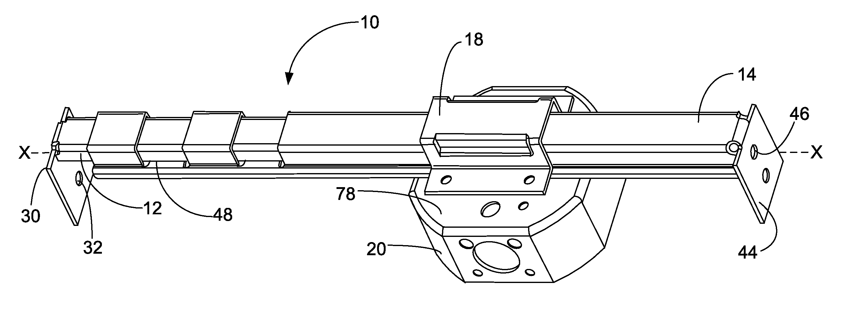
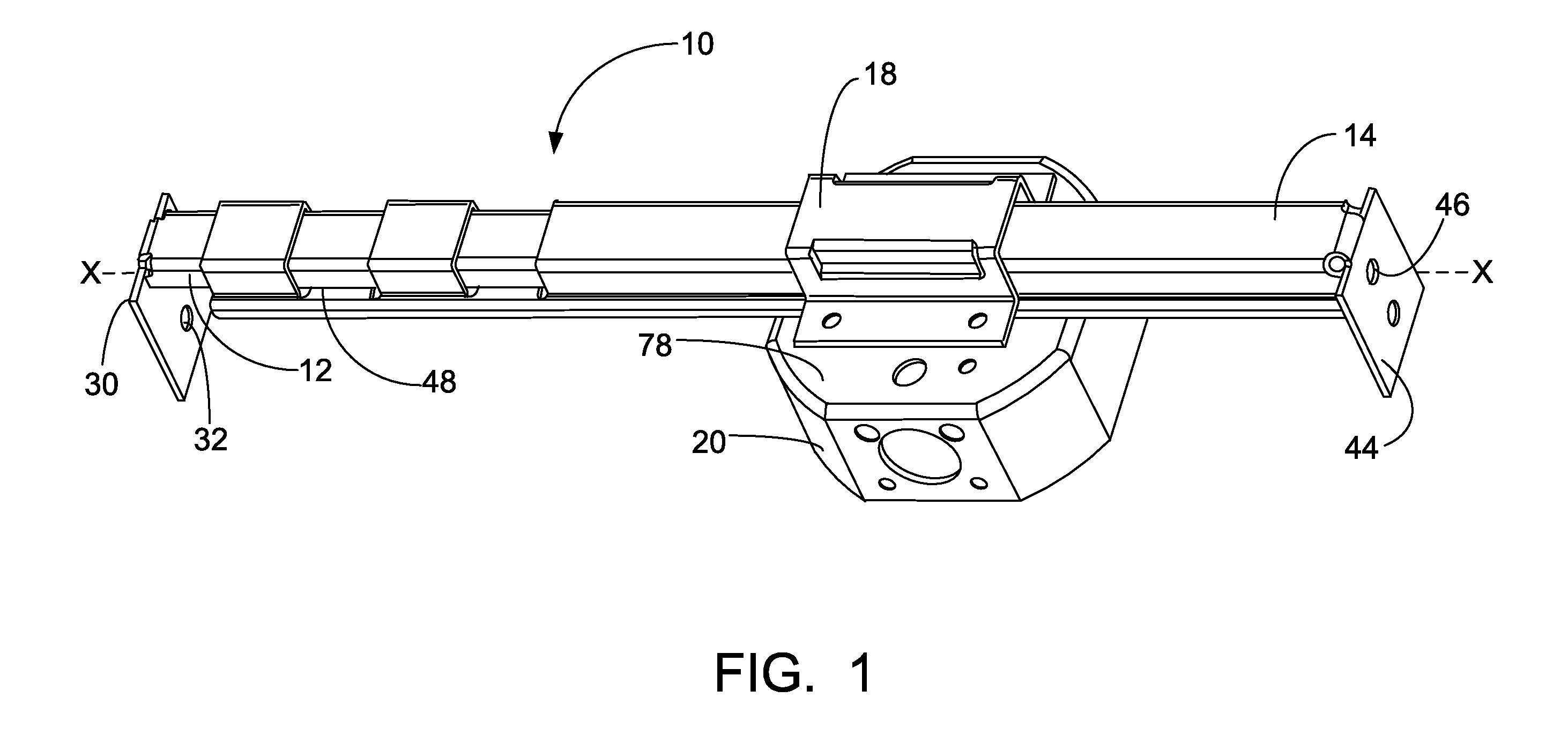
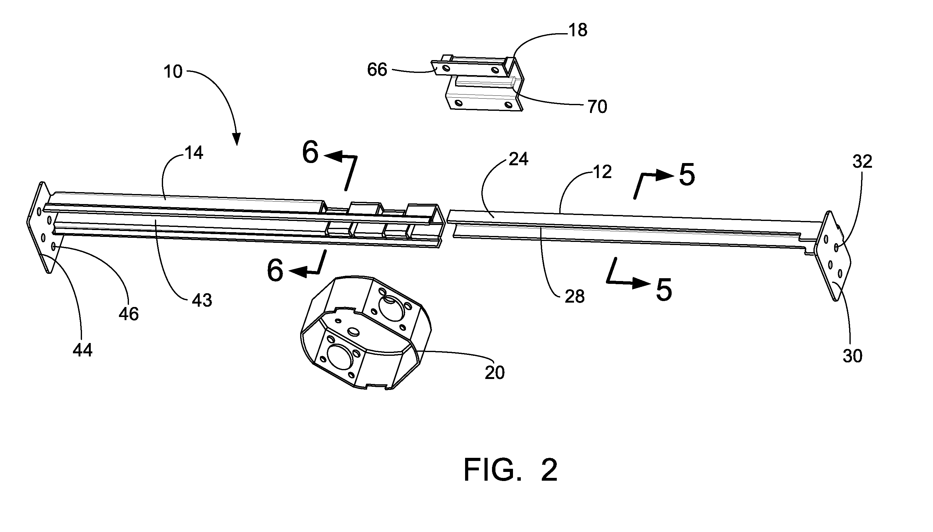
[0026]Referring to FIGS. 1-3, a hanger bar assembly 10 formed in accordance with a preferred embodiment of the present invention is shown. The hanger bar assembly 10 includes an elongate first member 12 which is telescopically engagable with an elongate second member 14. The first 12 and second 14 members are slidable with respect to each other. This permits the overall length of the assembly 10 to be adjusted so that the assembly may be secured between two support structures 16 such as ceiling joints, wall joists, or other spaced members. The first 12 and second 14 members are preferably dimensioned so that the assembly 10 can be adjusted to fit between the standard 16 inch and 24 inch center-on-center spacing of joists. However, it is within the contemplation of the present invention that the length of the first and second members could be made to accommodate a wide variety of spacings. An electrical box bracket 18 is positioned over the elongate members and provides an attachment...


PUM

PropertyMeasurementUnit
electricaaaaaaaaaa
lengthaaaaaaaaaa
weightaaaaaaaaaa

Abstract

An adjustable hanger bar assembly securable to a support structure including an elongate first member and an elongate second member. The first member is telescopically received within the second member. A securement section is supported on the second member. The securement member captures the first member within the second member and permits relative movement between the first and second members in a direction along a longitudinal axis of the first and second members, and restricts motion between the first and second members in a direction transverse to the longitudinal axis.

Description

[0001]This application claims priority to U.S. provisional application Ser. No. 60 / 887,475 filed on Jan. 31, 2007, which is incorporated by reference herein in its entirety for all purposes.FIELD OF INVENTION[0002]The present invention relates generally to an adjustable hanger bar assembly for supporting electrical fixtures. More particularly, the present invention relates to a hanger bar assembly having telescopically engaged members.BACKGROUND OF THE INVENTION[0003]In order to secure electrical fixtures such as lights and fans in ceilings, a hanger bar device is typically employed. It is very important that a fixture be adequately supported in the ceiling since improper support could lead to the fixture breaking away from the ceiling. Ceilings are typically constructed of structural members including a series of spaced joists which are covered by lathe and plaster or a gypsum wallboard. The ceiling covering material or sheathing is not designed to support loads perpendicular to it...

Claims


Application Information

Patent Timeline
Patent Type & Authority Patents(United States)
IPC IPC(8): B42F13/00
CPCH02G3/125Y10T29/49826Y10S248/906
Inventor DE LA BORBOLLA, IAN RUBIN
Owner THOMAS & BETTS INT INC
Why Eureka
Try Eureka