Knitting needle with ergonomic configuration

a knitting needle and ergonomic technology, applied in knitting, weft knitting, textiles and papermaking, etc., can solve the problem of little benefit derived by applying elevation changes, and achieve the effect of convenient and comfortable knitting, easy and fast knitting, and convenient knitting and knitting process

Inactive Publication Date: 2011-01-25
LINDAHL STEVEN M
View PDF39 Cites 29 Cited by
  • Summary
  • Abstract
  • Description
  • Claims
  • Application Information

AI Technical Summary

Benefits of technology

[0014]It is the primary object of this invention to provide a hand-held tool that knitters can use to make the knitting process more comfortable and enjoyable. It is also an object of this invention to provide a hand-held tool for knitting that is more easily and comfortably held by knitters' fingers during new loop / stitch creation. Another object of this invention is to provide knitting needles with a more ergonomic configuration at least in the areas of its shaft generally held by knitters new loop / stitch creation and stitch / loop transfer. A further object of this invention is to provide a hand-held tool for easier and faster knitting by those having arthritic hands and / or joint problems in the fingers, hands, or wrists. It is also an object of this invention to provide a tool for extending the duration of comfortable knitting by decreasing finger and hand fatigue from the outset of use. In addition, it is an object of this invention to provide knitting needles with decorative enhancement that also provides ergonomic benefit.

Problems solved by technology

However, although elevation changes similar to those used on the rigid members could also be used on the smaller-diameter flexible filament extending between the two rigid members, the filament portion of a circular needle is not typically held by knitters and there would be little benefit derived by applying elevation changes to it, other than for decorative purposes, such as but not limited to providing a decorative pattern extension of, or contrast to, the pattern or patterns established by elevation changes associated with the rigid members.

Method used


Image

  • Knitting needle with ergonomic configuration
  • Knitting needle with ergonomic configuration
  • Knitting needle with ergonomic configuration

Examples


Embodiment Construction

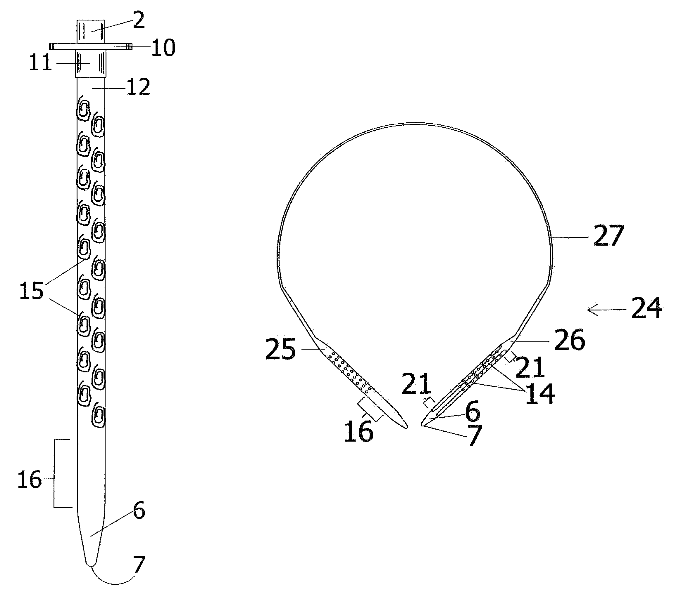
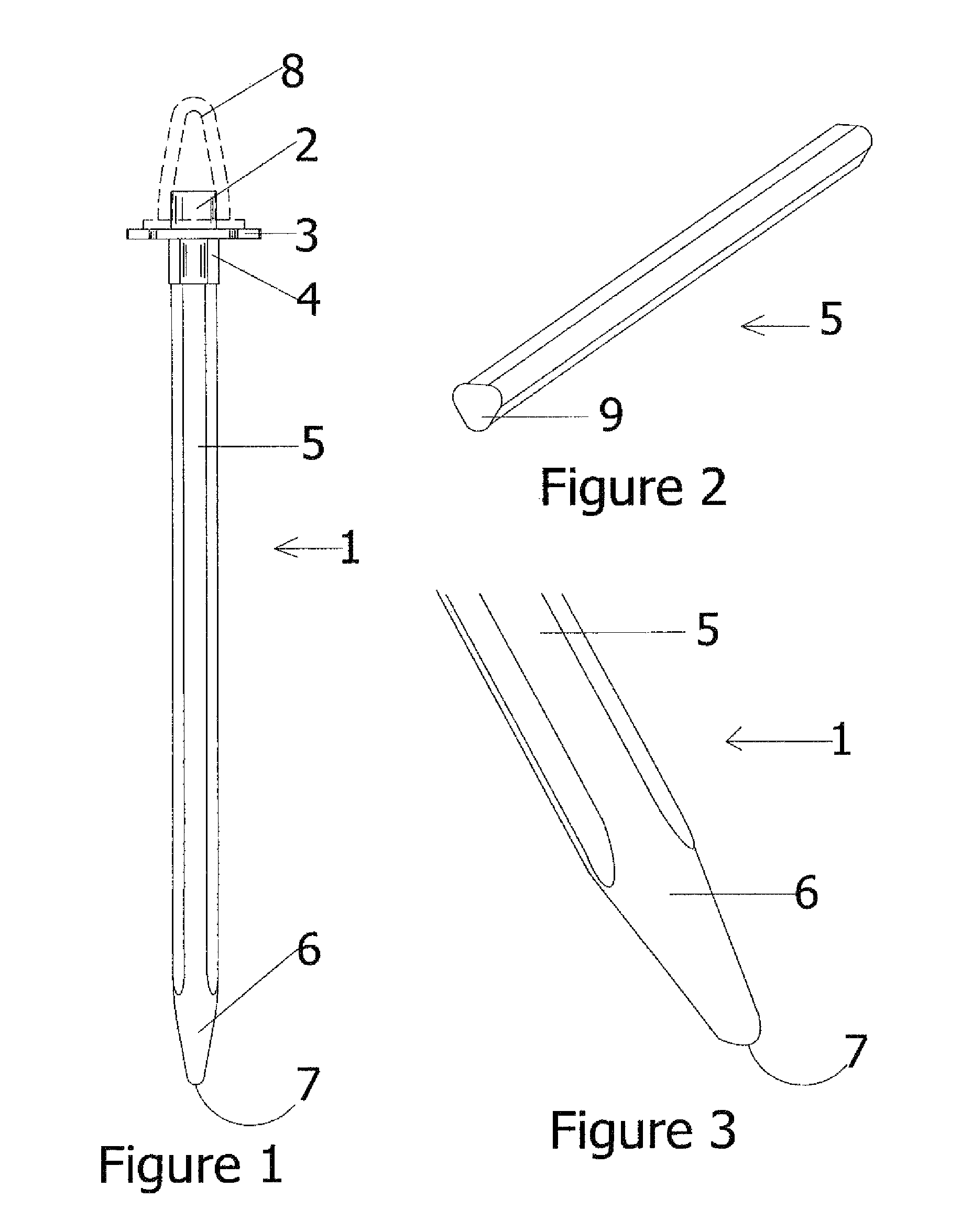
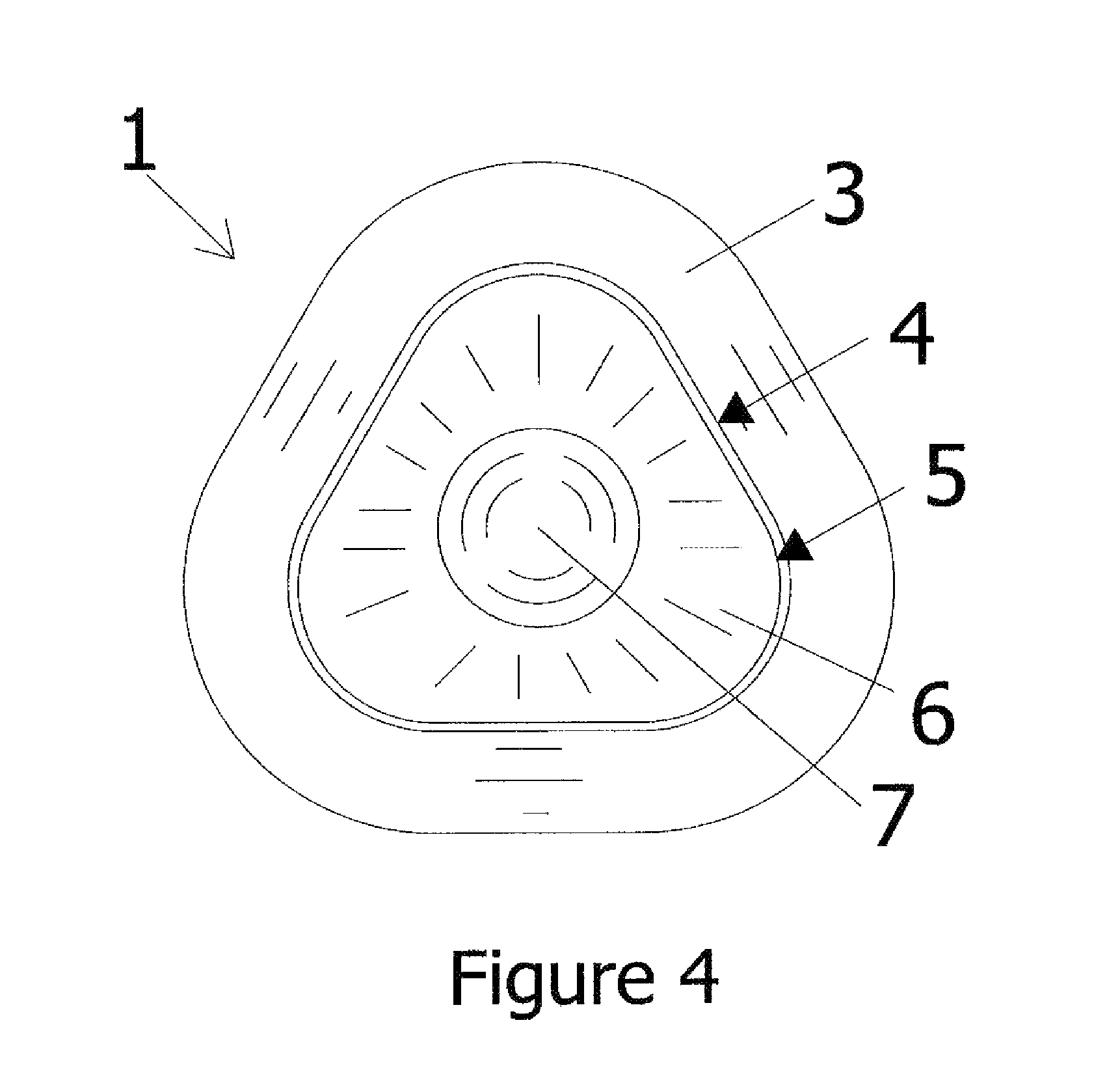
[0064]Knitting needles traditionally have a shaft with a circular cross-section and a smooth exterior surface, and come in standard sizes for predictability in the size of a finished product when printed knitting instructions are followed. They also may be in the form of a single-point needle having an elongated rigid shaft and a stitch-preserving end cap on its non-working (non-stitch-transferring) end, a double-point needle having an elongated rigid shaft and two working ends, or a circular knitting needle having two rigid members (shortened shafts) each with a pointed loop-transferring tip / end, with the two rigid members joined to one another via an elongated flexible filament generally of reduced diameter dimension. The knitting process is accomplished by using the pointed ends / tips 7 of the knitting needles to draw one or more new loops through a series of loops previously placed on a knitting needle shaft 5, involving one or more of the prior loops at a time, with twisting and...


PUM


Abstract

A knitting needle with one or more elevation changes that provide ergonomic benefit on the portions of its shaft typically held by knitters during stitch / loop creation, to allow knitting with enhanced comfort, faster knitting, and / or knitting for longer periods of time with less risk of hands becoming prematurely tired, numb, or aching from the repetitive motion inherent in knitting activity. The needle may also have different cross-sectional configurations that provide additional ergonomic benefit, in place of the traditional circular shape still most commonly used. The elevation changes are not positioned on the pointed tip of the needle, or within approximately one-and-one-half to two inches thereof, and are not so configured or pronounced as to interfere with the easy movement of stitches along the needle's shaft. A tube or post may further be added to the end cap on the non-pointed end of a single-point needle for convenient point protector mounting.

Description

CROSS-REFERENCES TO RELATED APPLICATIONS[0001]This patent application claims domestic priority from U.S. design patent application No. 29 / 325,343, filed by the same inventor for similar subject matter on Sep. 29, 2008 and having the title of “Knitting Needle With Ergonomic Configuration”. In addition, this patent application also claims domestic priority from U.S. design patent application No. 29 / 325,345, filed by the same inventor for similar subject matter on Sep. 29, 2008 and having the title of “Knitting Needle Cap With Point Protector Mounting Projection”. All benefit of these previously filed pending U.S. applications to which the applicant is entitled is herein requested.BACKGROUND[0002]1. Field of the Invention[0003]This invention relates to elongated hand-held instruments or tools with at least one pointed end that are used for knitting yarn, fibers, strands and / or other elongated filamentous material into two-dimensional and three-dimensional shapes via the repeated pullin...

Claims


Application Information

Patent Timeline
Patent Type & Authority Patents(United States)
IPC IPC(8): D04B3/02
CPCD04B3/02
Inventor LINDAHL, SANDRA KAY
Owner LINDAHL STEVEN M
Why Eureka
Try Eureka