Systems and methods for area denial

a technology of system and method, applied in the field of system for area denial, can solve the problems of ineffective deployment of force, failure or failure of conventional area denial, and insufficient accuracy of force deployment,

Inactive Publication Date: 2011-02-15
AXON ENTERPRISE INC
View PDF6 Cites 47 Cited by
  • Summary
  • Abstract
  • Description
  • Claims
  • Application Information

AI Technical Summary

Problems solved by technology

Conventional area denial fails or is considered unsuccessful when a suitable target passes through the denial zone.
Failure may be due to ineffective deployment of force to stop the intrusion or due to insensitivity.
Force may be ineffective when deployed with insufficient accuracy.
In addition, conventional area denial systems generally suffer from a high incidence of false alarms.
A false alarm is an event where force is deployed but no suitable target is available to effect meaningful denial.
The target may not be a suitable target, for example, where an area denial system is planned against human intruders but responds inappropriately to animals, wind blown foliage, or changes in surface illumination.
Insensitivity may occur when the target goes undetected, is misclassified as an unsuitable target, or is erroneously determined to be unavailable (e.g., cannot be acquired by targeting technology).
These systems are generally expensive because it is difficult to staff alert human operators.
These systems are subject to failure to actually accomplish area denial for example due to operator insensitivity.
There remains a significant probability of unsuccessfully denying passage of a suitable target through the zone.
Further, the force taught by McNulty is known to be insufficient to halt locomotion by a human or animal target.
These systems are capable of denying access (e.g., denying opening a door to a nonemployee) but are not capable of deploying force to deny movement through a denial zone.
These technologies are not sufficient to meet significant demand for high safety and high security installations.
New applications for area denial cannot be met with conventional area denial technologies.
For example, if conventional area denial technology was to be used in a prison, or near a utility substation having dangerous equipment, lethal force would be unwarranted; and mere notice of intrusion may be insufficient to accomplish the intended safety and / or security purposes.
Conventional nonlethal area denial systems are inaccurate and subject to high incidence of false alarms and insensitivity.

Method used


Image

  • Systems and methods for area denial
  • Systems and methods for area denial
  • Systems and methods for area denial

Examples


Embodiment Construction

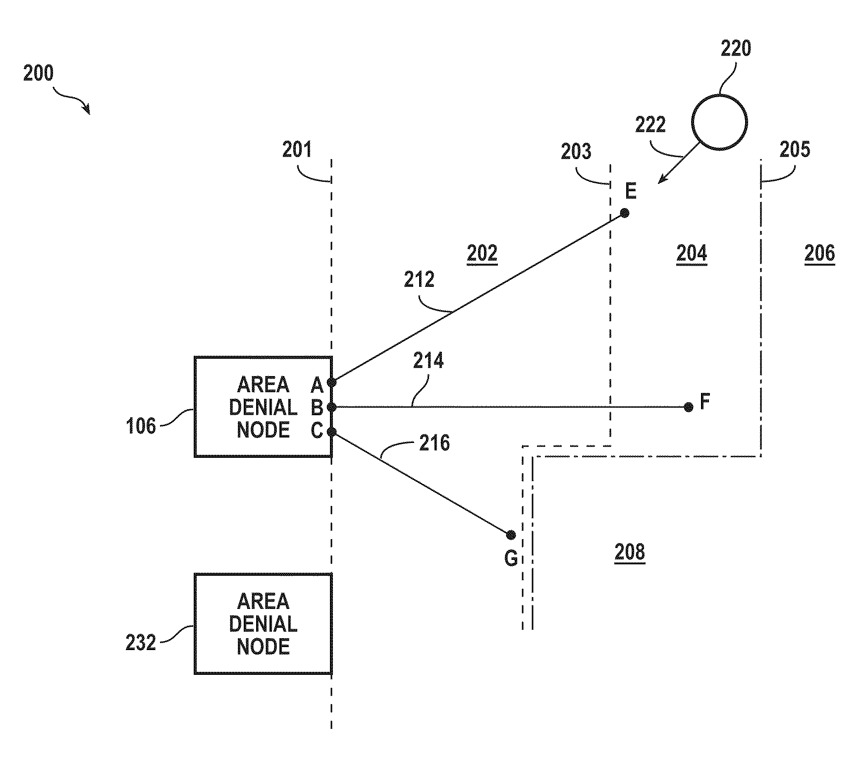
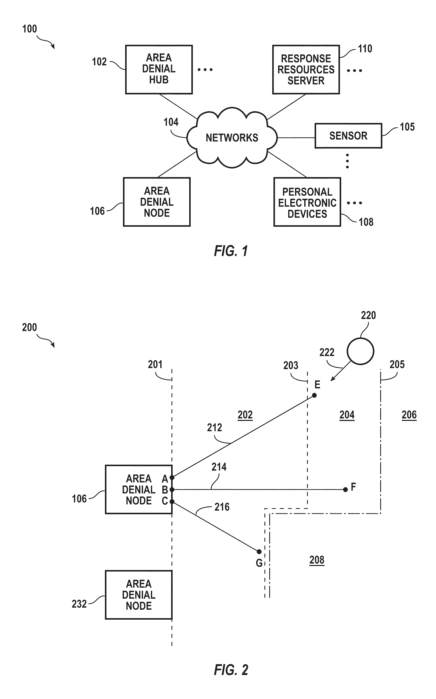
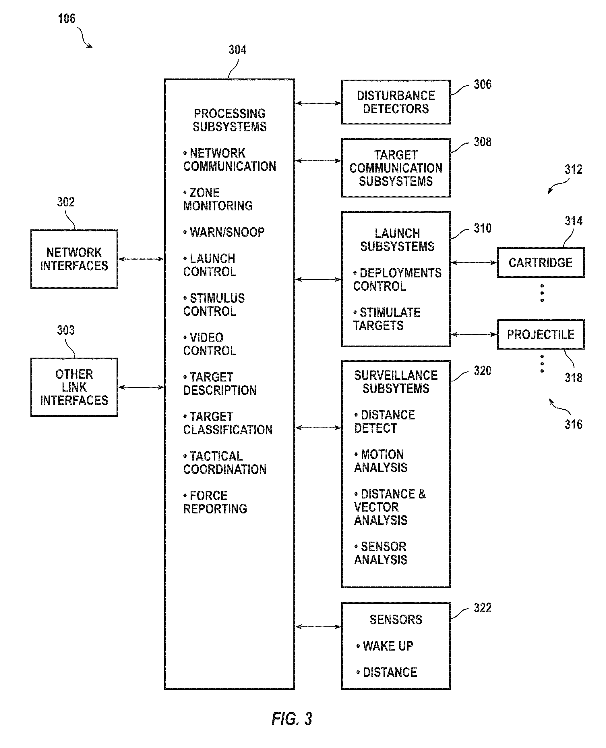
[0030]An area denial system, according to various aspects of the present invention, inhibits locomotion of a human of animal target with respect to a zone. Successful area denial may be complete as to a traget; or, incomplete yet sufficient as to a target. Inhibiting includes deterring further voluntary movement with respect to the zone. Inhibiting includes pain compliance (e.g. sufficiently interfering with locomotion) and / or immobilization (e.g., halting locomotion). Force used to inhibit may be applied to cause pain and / or to immobilize. Immobilization may include electrically disrupting the target's voluntary control of its skeletal muscles. An amount of force applied may be determined with respect to a classification of the target (e.g., kind of animal, human, size), present location of the target (e.g., more force at locations deeper within the zone), and / or velocity and direction of movement of the target. In a simpler implementation, the same force may be used against all cl...


PUM


Abstract

Systems and methods inhibit locomotion of a human or animal target in a denial zone. Acquiring the target includes forming a prediction of at least two locations of impact on the target and testing the prediction according to criteria that may include whether the locations are within a boundary corresponding to the target and whether the locations are separated by a minimum physical and / or electrical distance.

Description

CROSS-REFERENCE TO RELATED APPLICATION[0001]This application claims the benefit under 35 U.S.C. §119(e) of U.S. patent application Ser. No. 60 / 850,057 to Kevin Williams, et al., filed Oct. 7, 2006.FIELD OF THE INVENTION[0002]Embodiments of the present invention relate to systems for area denial and methods performed by systems for area denial.BACKGROUND OF THE INVENTION[0003]Conventional area denial technology has been applied, for example, in military settings to deny personnel and vehicles from passing across a particular surface area called a denial zone. Passage of a target into the denial zone is detected by object proximity technologies including trip wires, acoustic sensors, compression plate sensors, and laser beam occlusion sensors. Denial may be accomplished by lethal force such as used in antipersonnel land mines, antivehicle land mines, and projectiles intended to strike the target. In some systems, denial may be automatic upon detecting a disturbance in the denial zone....

Claims


Application Information

Patent Timeline
Patent Type & Authority Patents(United States)
IPC IPC(8): F41B15/04
CPCF41H13/0025F41H13/0031Y10S119/908
Inventor WILLIAMS, KEVINBALDWIN, CHRISTOPHER WALLACESHEKARRI, NACHE D.
Owner AXON ENTERPRISE INC
Why Eureka
Try Eureka