Flash suppressor

Inactive Publication Date: 2011-03-15
JJE BRANDS LLC
View PDF11 Cites 41 Cited by
  • Summary
  • Abstract
  • Description
  • Claims
  • Application Information

AI Technical Summary

Benefits of technology

[0011]More specifically, a preferred embodiment according to the invention provides a flash suppressor apparatus which may or may not serve as a fixture for a noise suppressor comprising the combination of; a bearing surface for a noise s

Problems solved by technology

The two aforementioned designs fail to provide several needed features necessary and desirable for today's firearms.
Muzzle flash is undesirable because it gives away the location of a shooter at night or under other low ambient light conditions.
Current flash suppressor designs utilizing open front tines are prone to expansion when a noise suppressor is mounted during prolong firing schedules.
This expansion is the result of substantial pressures and heat exposure and metal fatigue.
An expansion of th

Method used


Image

  • Flash suppressor

Examples


Example

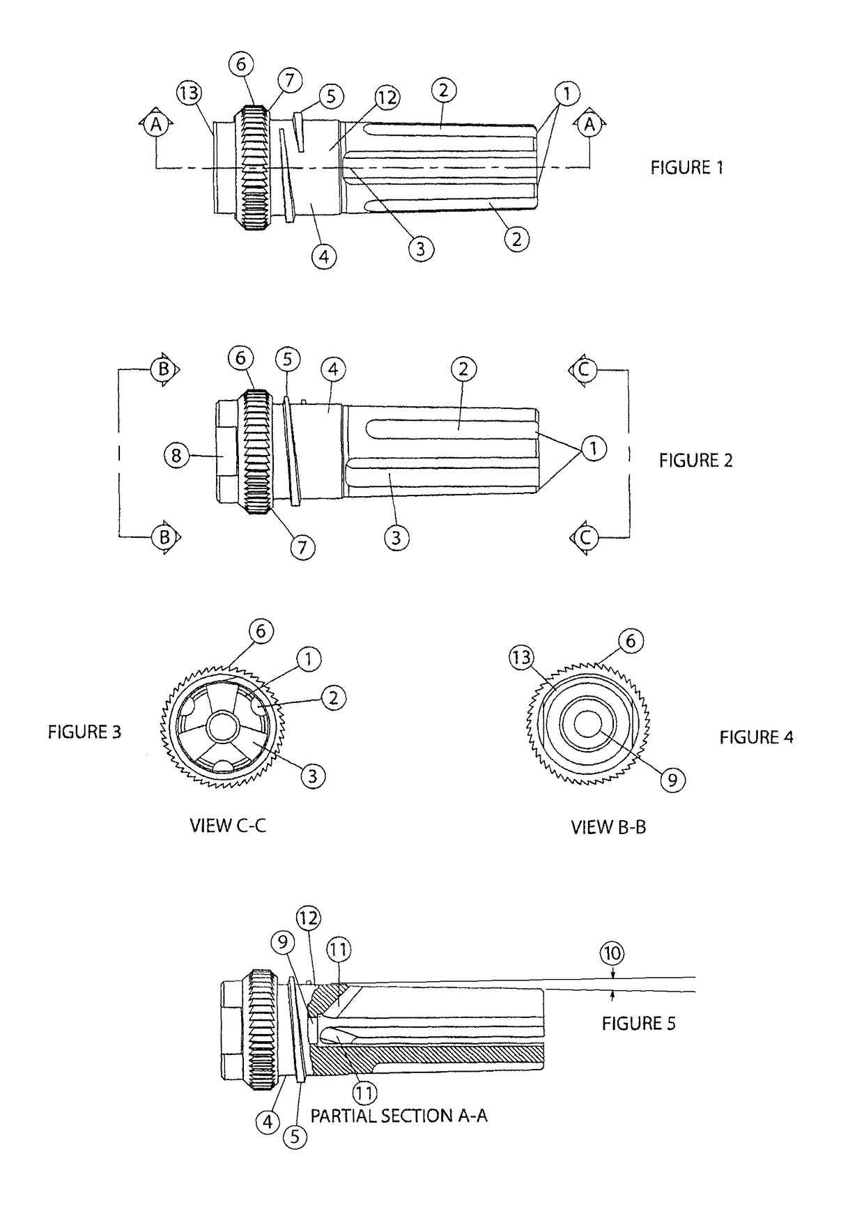
[0020]Heat treatable stainless steel is used to construct the flash suppressor. Certain alloys of stainless steel may be heat treated for additional strength. Properly selected stainless steel alloys, when used in the manufacture of firearm parts, can maintain machined or cast structure under temperatures up to 1200 degrees, which is an important consideration due to the firing schedules modern firearms are often subjected to.

[0021]The flash suppressor is manufactured using a lathe and mill to complete both circular and plunge cuts which are necessary for its construction.

[0022]FIGS. 1-5 show the preferred embodiment of the present invention. It depicts a flash suppressor 12 configured for use with standard United States military weaponry, particularly the AR-15 and M-16 firearms. These firearms have a standard bore of .223 caliber (5.56 mm). Such firearms have a barrel with a conventional male threaded extension. Flash suppressor 12 generally includes a cylindrical socket 13 which ...


PUM


Abstract

An improved flash suppressor and silencer mount. The use of tapered tines allows for the easy removal of a noise suppressor from the flash suppressor even after extended use. Due to the construction of the flash suppressor and through proper material selection the tines will not warp or break even after being exposed to temperatures in excess of 1100 degrees. Through the use of angled concave transition portions this device is a superb stand alone flash suppressor.

Description

BACKGROUND OF THE INVENTION[0001]1. Field of Invention[0002]This invention generally relates to firearms muzzle devices, specifically to devices commonly referred to as flash suppressors / flash hiders which are affixed to the muzzle of a firearm barrel for the purpose of reducing flash associated with the discharge of the host firearm.[0003]2. Prior Art[0004]Various systems exist for reducing the muzzle flash of a firearm with it has been discharged. Previous designs provide a combination of features which culminated in a system for reducing the muzzle flash of a firearm to various degrees. BE Meyers four tine design (as patented in Meyers U.S. Pat. No. 6,837,139 and Meyers U.S. Pat. No. 7,302,774) and the Smith Enterprises Vortex flash suppressor (as patented in Sommers U.S. Pat. No. 5,596,161) are two popular designs currently available. The two aforementioned designs fail to provide several needed features necessary and desirable for today's firearms.[0005]Muzzle flash occurs as a...

Claims


Application Information

Patent Timeline
IPC IPC(8): F41A21/00
CPCF41A21/325F41A21/34
Inventor BRITTINGHAM, KEVIN TYSONSILVERS, ROBERT
Owner JJE BRANDS LLC
Why Eureka
Try Eureka