

Pulling Grips for Installing a Fiber Optic Assembly
- Summary
- Abstract
- Description
- Claims
- Application Information
AI Technical Summary
Benefits of technology
Problems solved by technology
Method used
Image

Examples
Embodiment Construction
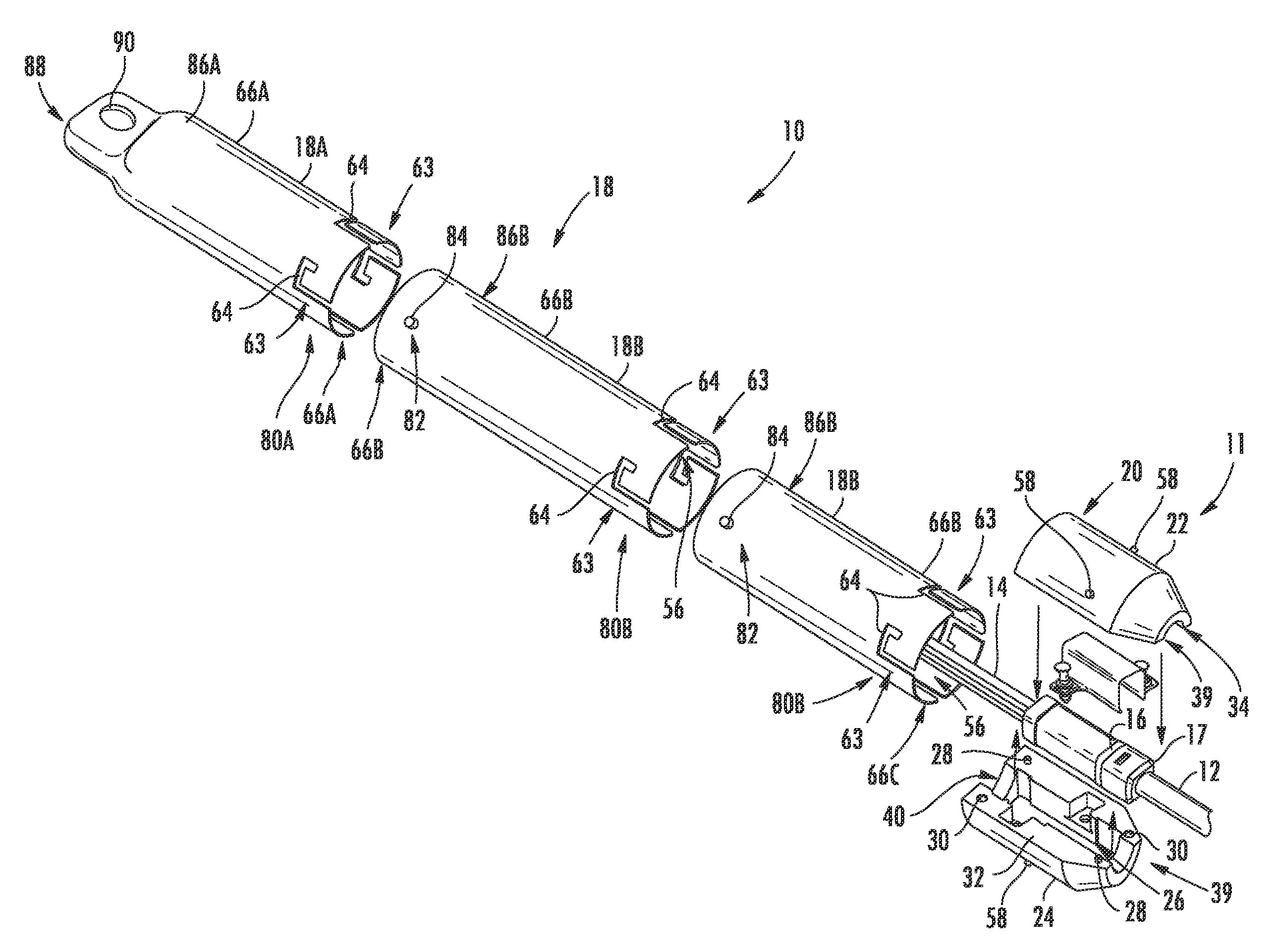
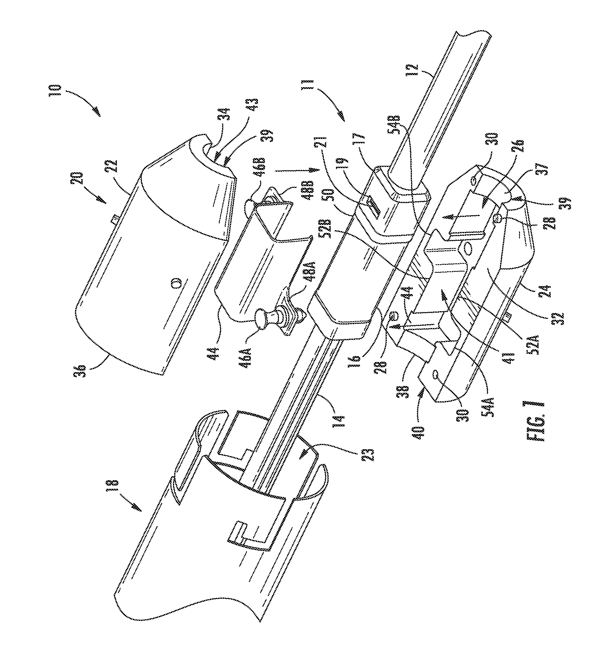
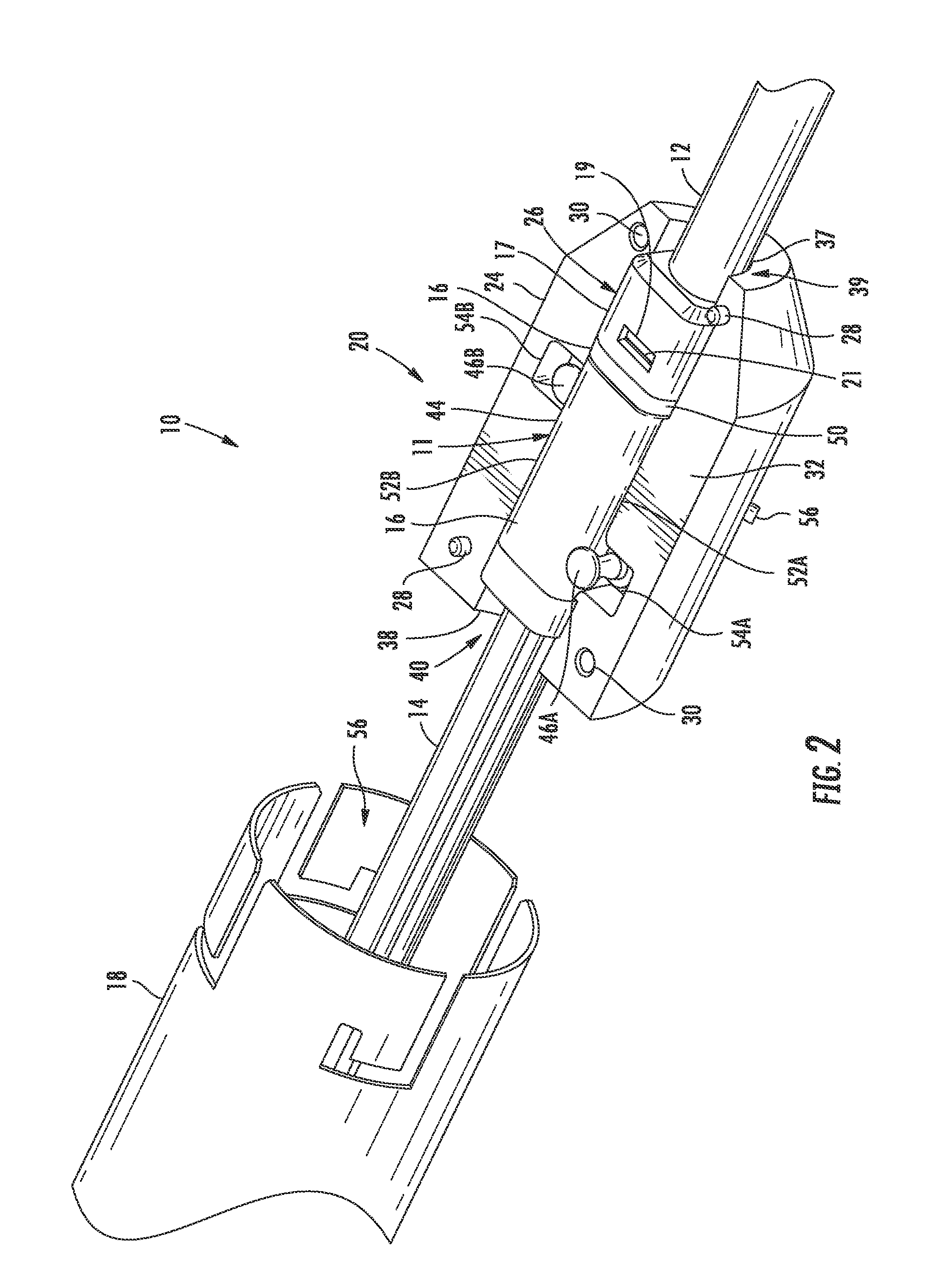
[0010]Embodiments disclosed in the detailed description include pulling grip assemblies or simply a pulling grip for installing a fiber optic assembly. In one embodiment, the pulling grip is comprised of a pulling grip housing for receiving part of a fiber optic assembly. A pulling grip sleeve is also provided. When assembled, one disclosed embodiment has a portion of the pulling grip housing is inserted into a portion of the pulling grip sleeve forming a friction fit therebetween. In this manner, the pulling grip housing is easily inserted into the pulling grip sleeve and easily, removed when pulling of a fiber optic assembly is completed. Moreover, the friction fit inhibits rotation of the pulling grip housing and the fiber optic assembly relative to the pulling grip sleeve when installing the fiber optic assembly, thereby inhibiting twisting of the fiber optic assembly during installation. A pulling sock is positioned and secured over the pulling grip sleeve and pulling grip hous...
PUM
 Abstract
Description
Claims
Application Information