Display drive apparatus, display apparatus and drive control method thereof
a technology of display apparatus and drive control method, which is applied in the direction of instruments, computing, electric digital data processing, etc., can solve the problems of difficult to stably realize a light-emitting operation for a long period, and achieve favorable and uniform display image quality
- Summary
- Abstract
- Description
- Claims
- Application Information
AI Technical Summary
Benefits of technology
Problems solved by technology
Method used
Image
Examples
first example
[0233]FIG. 17 is a timing chart illustratively showing a first example of the display drive method of the display apparatus according to the embodiment.
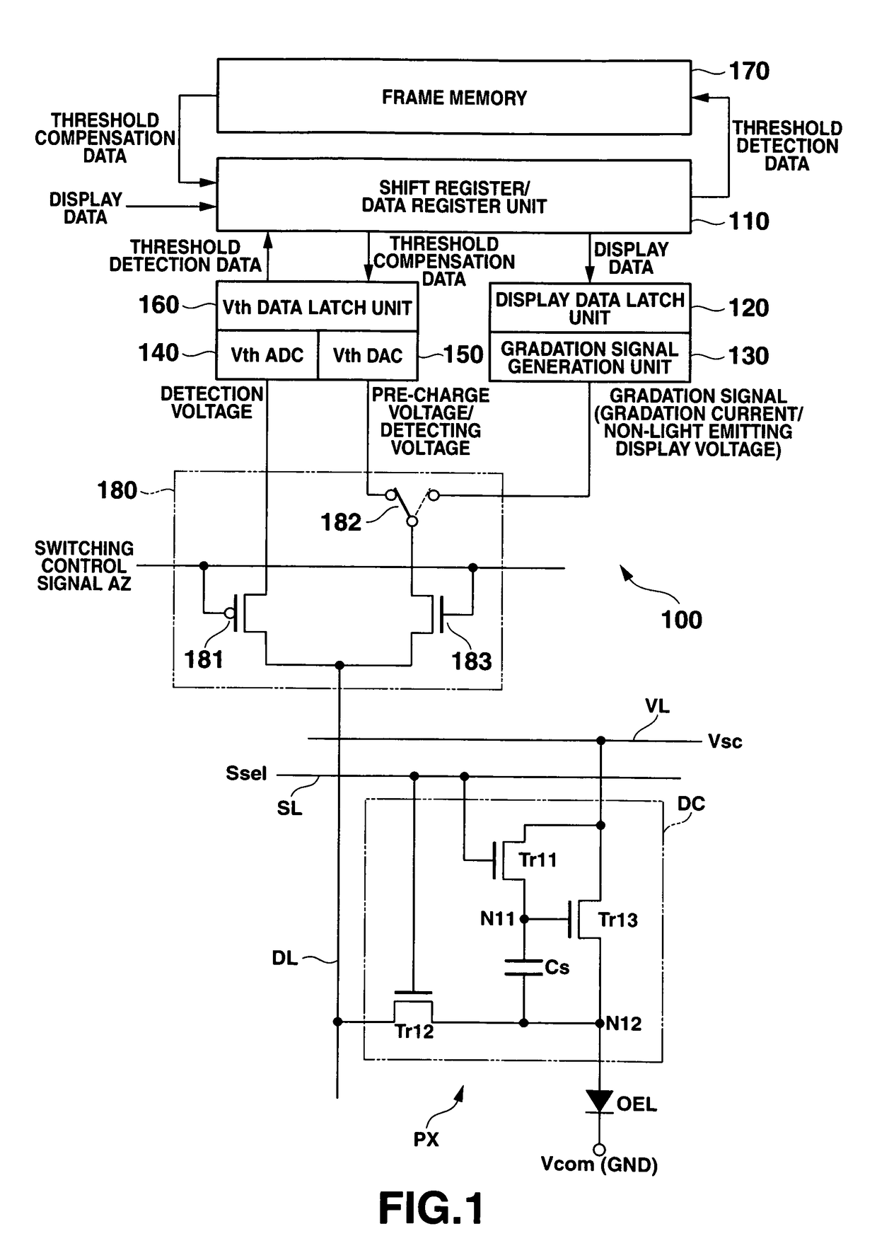
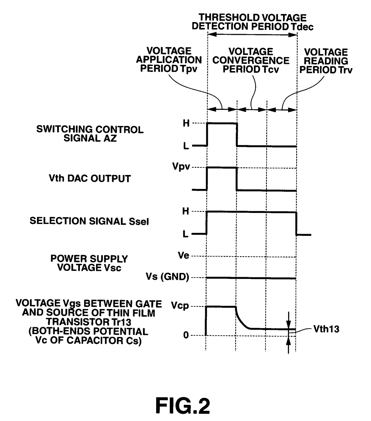
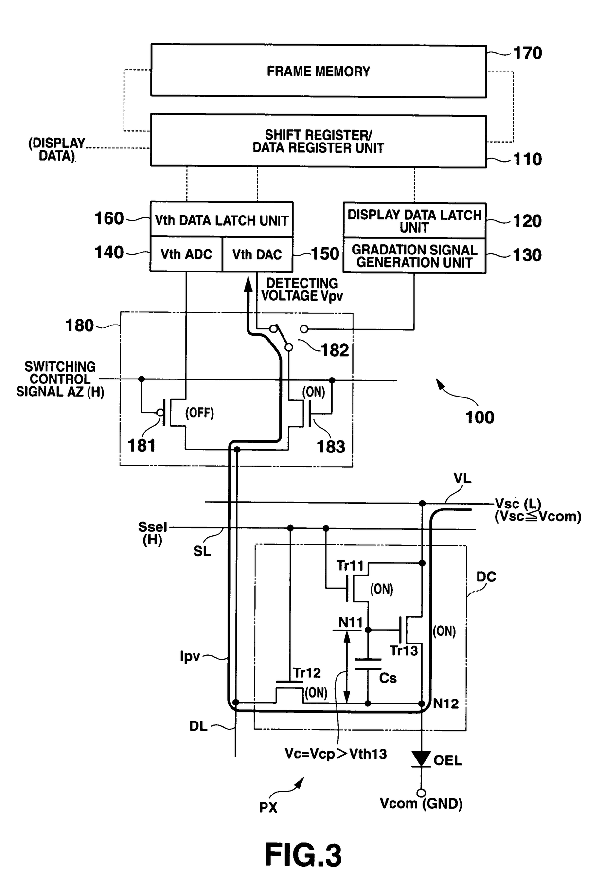
[0234]Here, an explanation will be omitted with respect to the drive control method (refer to FIGS. 2 and 7) which is the same as the case in the display drive apparatus and the display pixel (the drive circuit) shown in the above-described embodiment.
[0235]Incidentally, for the sake of explanation, the present embodiment has conveniently explained that a configuration is provided in which twelve rows (the first to twelfth rows) of display pixels are arranged. However, it goes without saying that the present invention is not limited thereto.
[0236]In the first example of the drive control operation of the display apparatus 200 according to the embodiment, generally, as shown in FIG. 17, a threshold voltage detection operation (a threshold voltage detection period Tdec) is first performed for detecting a threshold voltage (or a voltage...
second example
[0259]Next, by referring to the drawings, there will be explained a second example of the drive control method which is applicable to the display apparatus according to the embodiment.
[0260]FIG. 18 is a timing chart illustratively showing the second example of the drive control method of the display apparatus according to the embodiment.
[0261]Here, an explanation is simplified with respect to the drive control method which is the same as the first example (refer to FIG. 17) described above. In addition, the hatching portion in the figures shows the same operation state as the first example described above.
[0262]In addition, FIG. 19 is a structural diagram of a primary part showing one example of a display apparatus for realizing the second example of the drive control method of the display apparatus according to the embodiment.
[0263]Here, the same components as those of the display apparatus shown in the embodiment described above will be explained by attaching the same reference nu...
third example
[0274]Next, there will be explained a third example of the drive control method which is applicable to the display apparatus according to the embodiment with reference to the drawings.
[0275]FIG. 20 is a timing chart illustratively showing the third example of the display control method of the display apparatus according to the embodiment.
[0276]Here, an explanation on the drive control method same as that of the second example (refer to FIG. 18) described above will be simplified.
[0277]As shown in FIG. 20, the third example of the drive control method of the display apparatus 200 according to the embodiment is configured in the same manner as the second example described above, such that the threshold voltage detection operation is sequentially performed at a predetermined timing for each row with respect to all the display pixels PX arranged on the display panel 210 prior to the display drive operation followed by sequentially performing for each group for sequentially performing, w...
PUM
 Abstract
Description
Claims
Application Information
 - R&D
- Intellectual Property
- Life Sciences
- Materials
- Tech Scout
- Unparalleled Data Quality
- Higher Quality Content
- 60% Fewer Hallucinations
Browse by: Latest US Patents, China's latest patents, Technical Efficacy Thesaurus, Application Domain, Technology Topic, Popular Technical Reports.
© 2025 PatSnap. All rights reserved.Legal|Privacy policy|Modern Slavery Act Transparency Statement|Sitemap|About US| Contact US: help@patsnap.com


