Display device and driving method for display device

a display device and driving method technology, applied in the direction of static indicating devices, semiconductor devices, instruments, etc., can solve the problems of difficult stably realizing the light emitting operation with a luminance, the above-mentioned light emitting properties and display image quality are easily deteriorated, and the display image quality is easily deteriorated. , to achieve the effect of favorable and uniform display image quality, easy manufacturing and low cos

Inactive Publication Date: 2008-07-31
CASIO COMPUTER CO LTD
View PDF9 Cites 93 Cited by
  • Summary
  • Abstract
  • Description
  • Claims
  • Application Information

AI Technical Summary

Benefits of technology

[0018]Particularly, when an amorphous silicon thin film transistor, whose manufacturing process is already established and which can be manufactured relatively easily and inexpensively, is applied to the thin film transistors composing the driving circuits provided to the display pixels, since a DC voltage is applied for a long time, a threshold voltage greatly fluctuates. For this reason, the above-mentioned light emitting properties and display image quality are easily deteriorated.
[0019]Therefore, in view of the above problems, it is an object of the present invention to provide a display device having a favorable and uniform display image quality which applies a driving current having a value suitable for display data so as to be capable of driving light emission of display pixels (light emitting elements) arranged on a display panel with a luminance gradation suitable for the display data, and a driving method for the display device.

Problems solved by technology

For this reason, it is difficult to stably realize the light emitting operation with a luminance gradation suitable for the display data for a long period.
As a result, display devices having a uniform display image quality cannot be provided.
For this reason, the above-mentioned light emitting properties and display image quality are easily deteriorated.

Method used


Image

  • Display device and driving method for display device
  • Display device and driving method for display device
  • Display device and driving method for display device

Examples


first embodiment

[0071]A display device and a driving method according to an embodiment of the present invention are described in detail below.

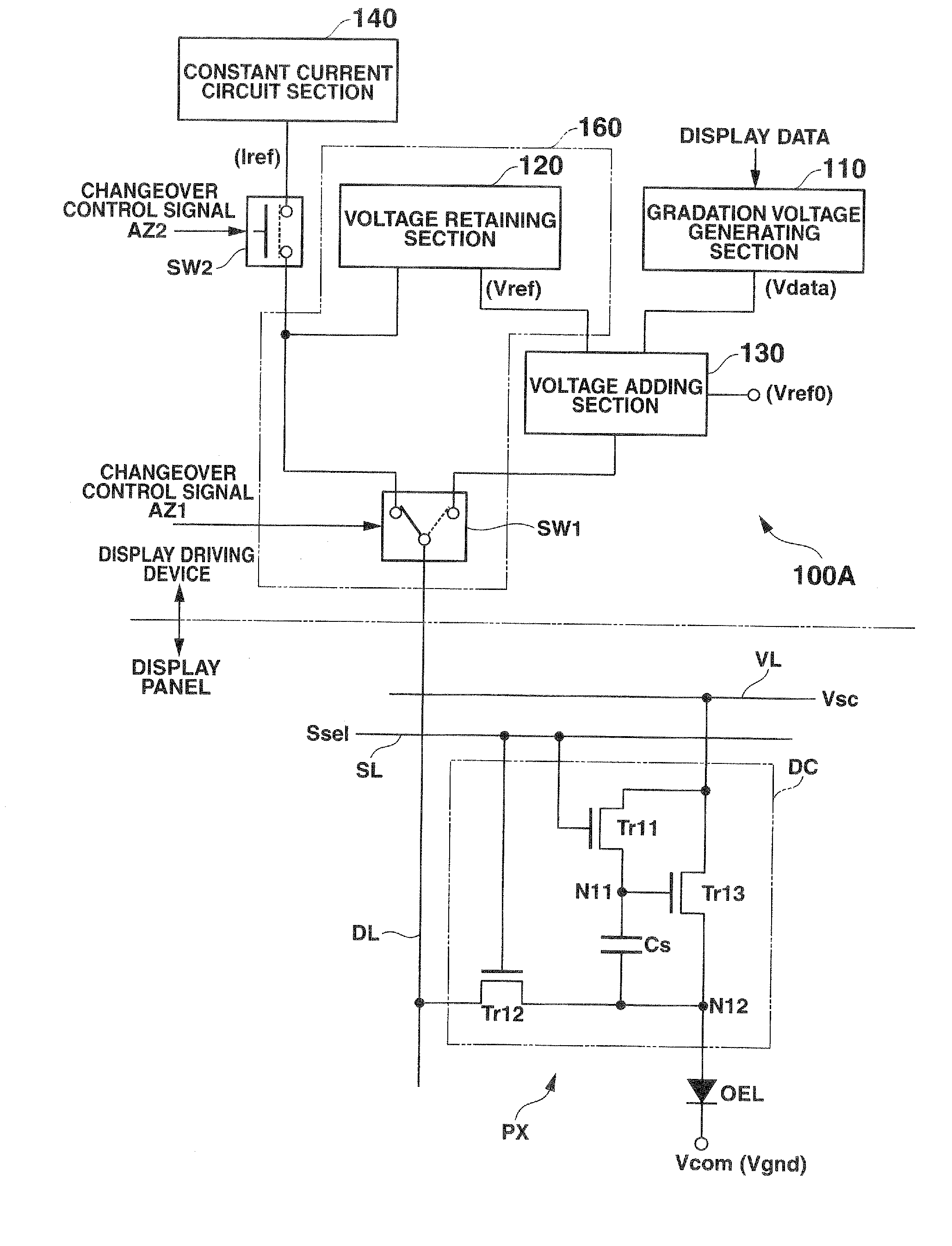
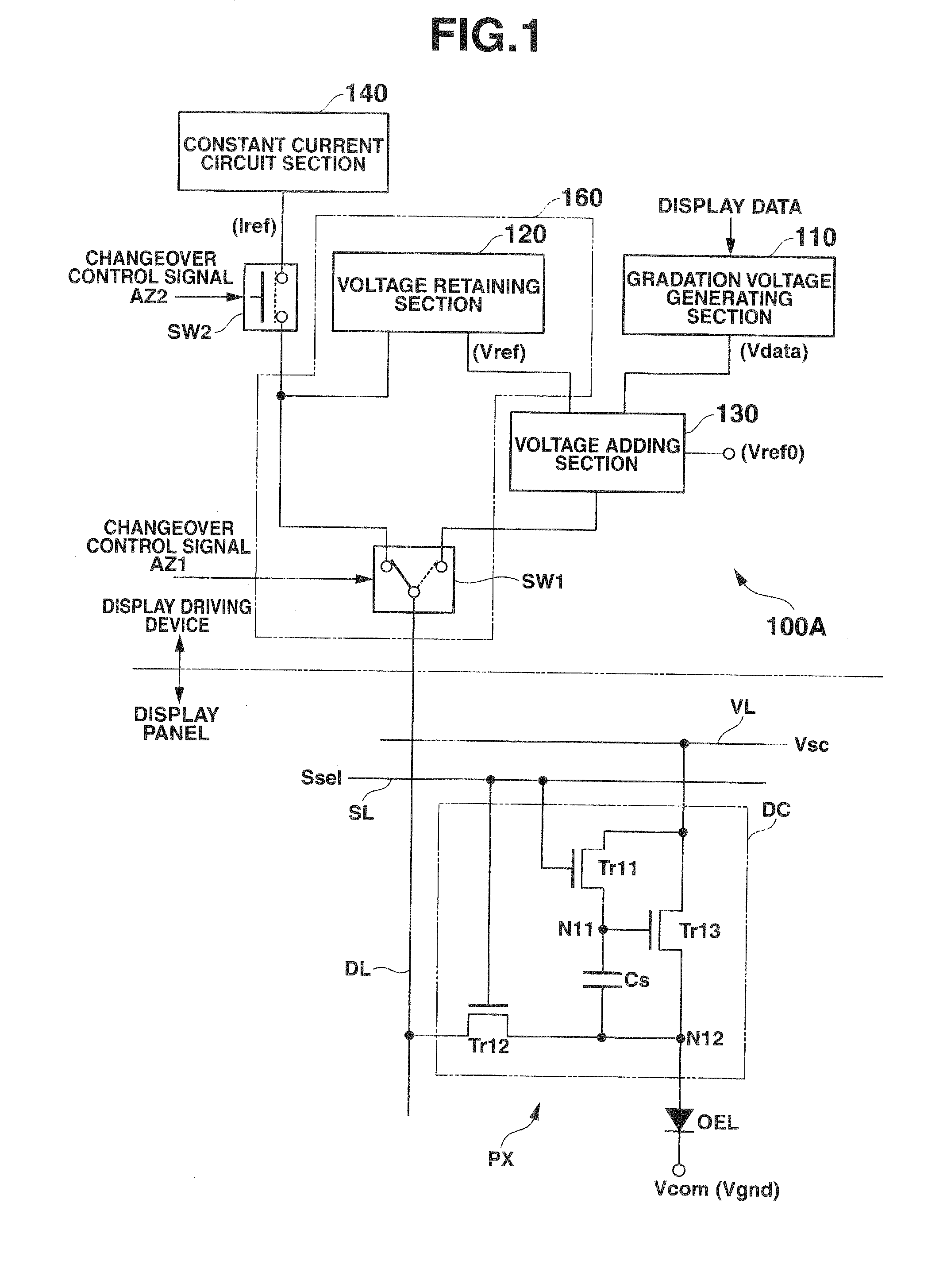
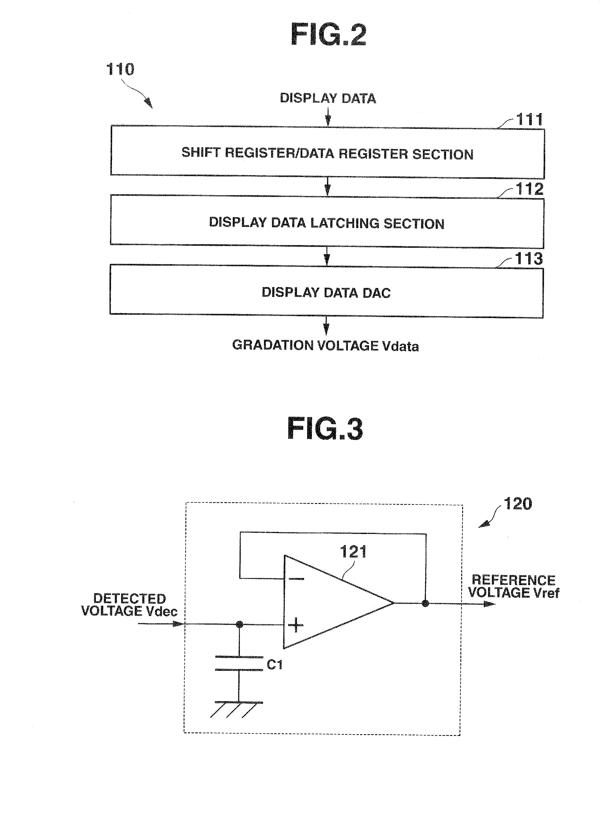
[0072]FIG. 1 is a main section constitutional diagram illustrating the display device according to the first embodiment of the present invention. A relationship between specified display pixels arranged on a display panel of the display device and a display driving device, which controls to drive light emission of the display pixels, is described in detail. FIG. 2 is a schematic block diagram illustrating one constitutional example of a gradation voltage generating section applied to the display device according to the first embodiment, and FIG. 3 is a schematic block diagram illustrating one constitutional example of a voltage retaining section applied to the display device according to the first embodiment.

[0073](Display Driving Device)

[0074]As shown in FIG. 1, a display driving device (data driving section) 100A which can be applied to the display device o...

second embodiment

[0148]FIG. 12 is a main section constitutional diagram illustrating the display section according to a second embodiment of the present invention. The constitution equivalent to that of the display device described in the first embodiment is designated by the equivalent or same reference numerals, and the description thereof is simplified.

[0149](Display Driving Device)

[0150]As shown in FIG. 12, in addition to the constitution (see FIG. 1) of the display driving device 100A according to the first embodiment, a display driving device (data driving section) 100B according to the second embodiment has a constant voltage circuit section (constant voltage supplying section) 150 which applies a constant voltage Vini having a predetermined value to the display pixel PX via the data line DL of the display panel, and a changeover switch SW3 which selectively switches over a connected state between the data line DL and the constant current circuit section 140 or the constant voltage circuit se...


PUM


Abstract

A display driving device includes a gradation voltage generating section which generates gradation voltage corresponding to display data, a constant current circuit section which supplies a predetermined constant current to a display pixel, a voltage detecting section which detects a voltage of a data line at the time of supplying the constant current as a detected voltage, and a voltage adding section which adds and subtracts the gradation voltage, a reference voltage corresponding to the detected voltage and an intrinsic voltage determined based on a design parameter of a driving transistor provided to the display pixel (driving circuit) so as to generate a pixel data voltage Vpix (=Vref−Vref0+Vdata), and supplies the pixel data voltage as a gradation signal to the data line.

Description

CROSS REFERENCE TO RELATED APPLICATIONS[0001]This is a Continuation Application of PCT Application No. PCT / JP2006 / 319170, filed Sep. 27, 2006, which was published under PCT Article 21 (2) in Japanese.[0002]This application is based upon and claims the benefit of priority from prior Japanese Patent Application No. 2005-279492, filed Sep. 27, 2005, the entire contents of which are incorporated herein by reference.BACKGROUND OF THE INVENTION[0003]1. Field of the Invention[0004]The present invention relates to a display device and a driving method for the display device, and particularly relates to a display device which includes a display panel (display pixel array) where a plurality of current-driven (or current-controlled) light emitting elements that emit light with a predetermined luminance gradation by supplying an electric current corresponding to display data are arranged, and the driving method for the display device.[0005]2. Description of the Related Art[0006]In recent years,...

Claims


Application Information

Patent Timeline
Patent Type & Authority Applications(United States)
IPC IPC(8): G09G3/30
CPCG09G3/3233G09G2300/0842G09G2320/043G09G2320/0295G09G2300/0866H01L2027/11879
Inventor OZAKI, TSUYOSHI
Owner CASIO COMPUTER CO LTD
Why Eureka
Try Eureka