Adjustable vehicle step

a vehicle step and adjustable technology, applied in the direction of vehicle components, steps arrangement, transportation and packaging, etc., can solve the problems of unadjustable one-piece devices, steps that do not allow for easy attachment, and consumers cannot be allowed to us

Inactive Publication Date: 2011-03-22
IRON CROSS AUTOMOTIVE
View PDF13 Cites 70 Cited by
  • Summary
  • Abstract
  • Description
  • Claims
  • Application Information

AI Technical Summary

Benefits of technology

[0009]The present invention is an adjustable vehicle step that attaches to the frame or body of the vehicle via a strong, downward facing c-channel that extends longitudinally along the lower edge of the side of the vehicle. The c-channel is bolted to the frame or body of the vehicle by metal supporting brackets that are welded to the side of the c-channel. One or more step assemblies can be attached to the c-channel via bolts that engage nuts that are captured within the c-channel by upwardly extending lips provided internally in the c-channel. Each step assembly is provided with a step portion that is welded on either end of

Problems solved by technology

One of the problems with the currently available vehicle steps is that they are one piece devices that are not adjustable as to where longitudinally on the vehicle the step must be attached.
Also, the currently available vehicle steps do not allow for easy attachment of multiple steps along the side of the vehicle.
Further currently available steps do not allow the co

Method used


Image

  • Adjustable vehicle step
  • Adjustable vehicle step
  • Adjustable vehicle step

Examples


Embodiment Construction

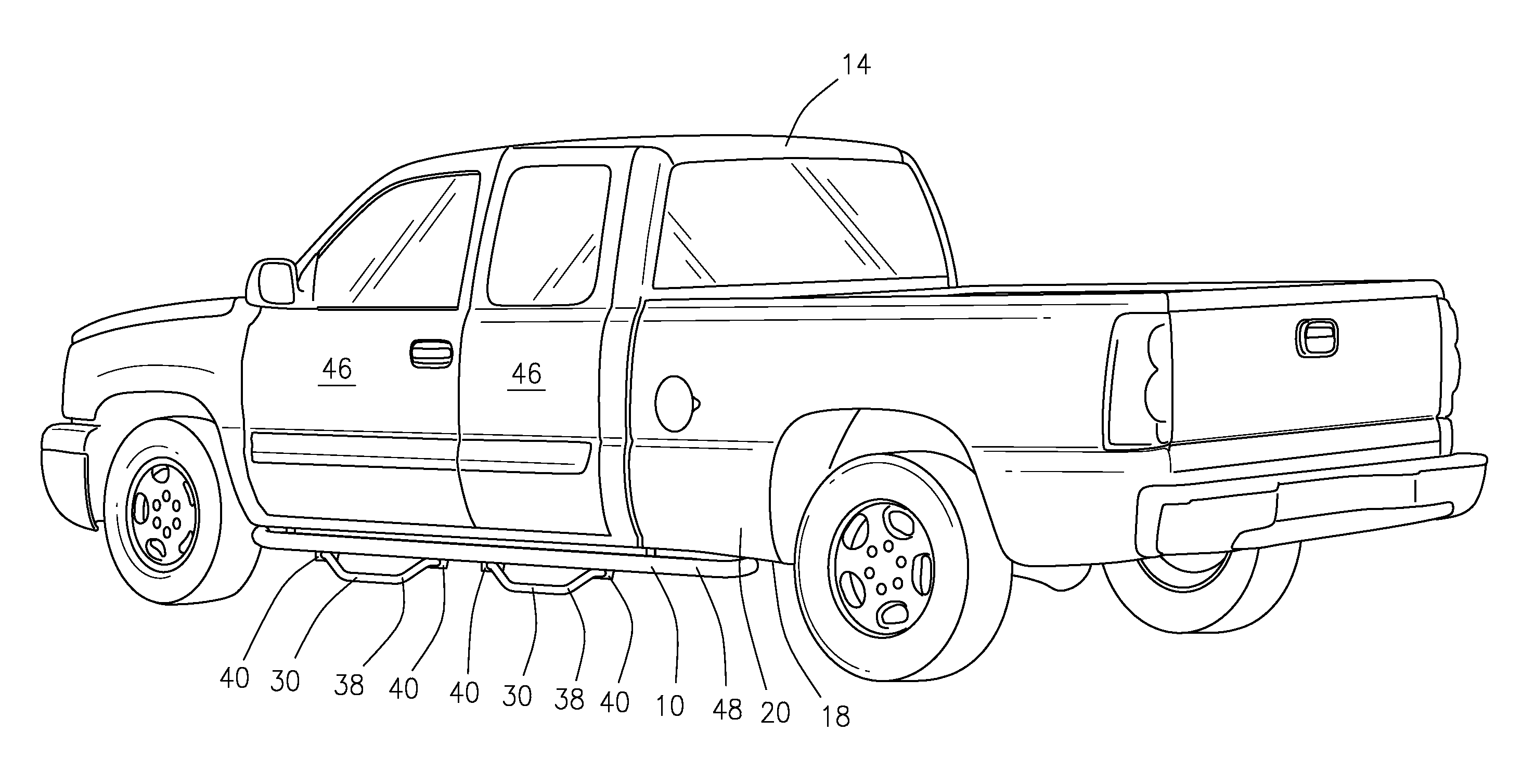
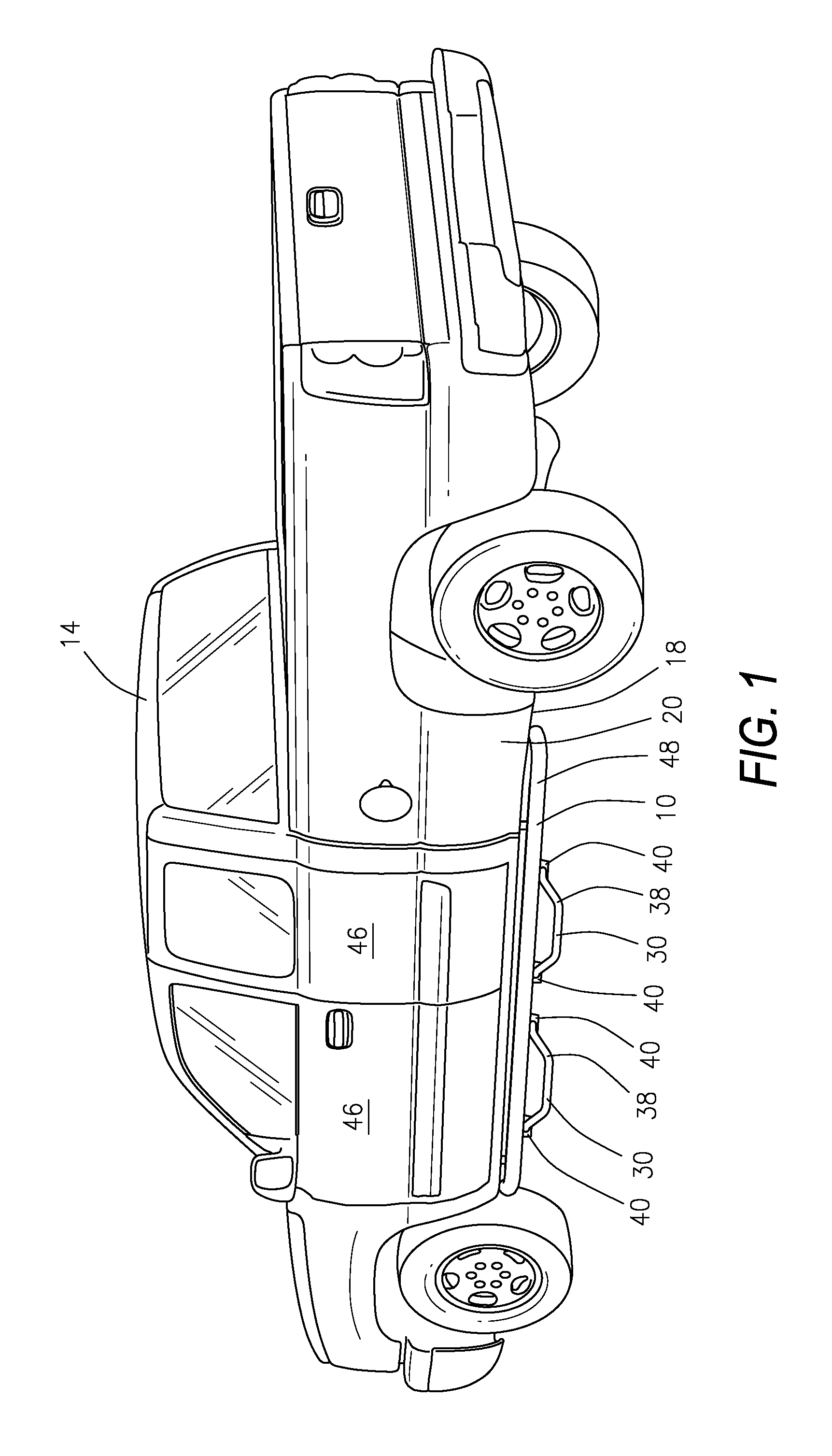
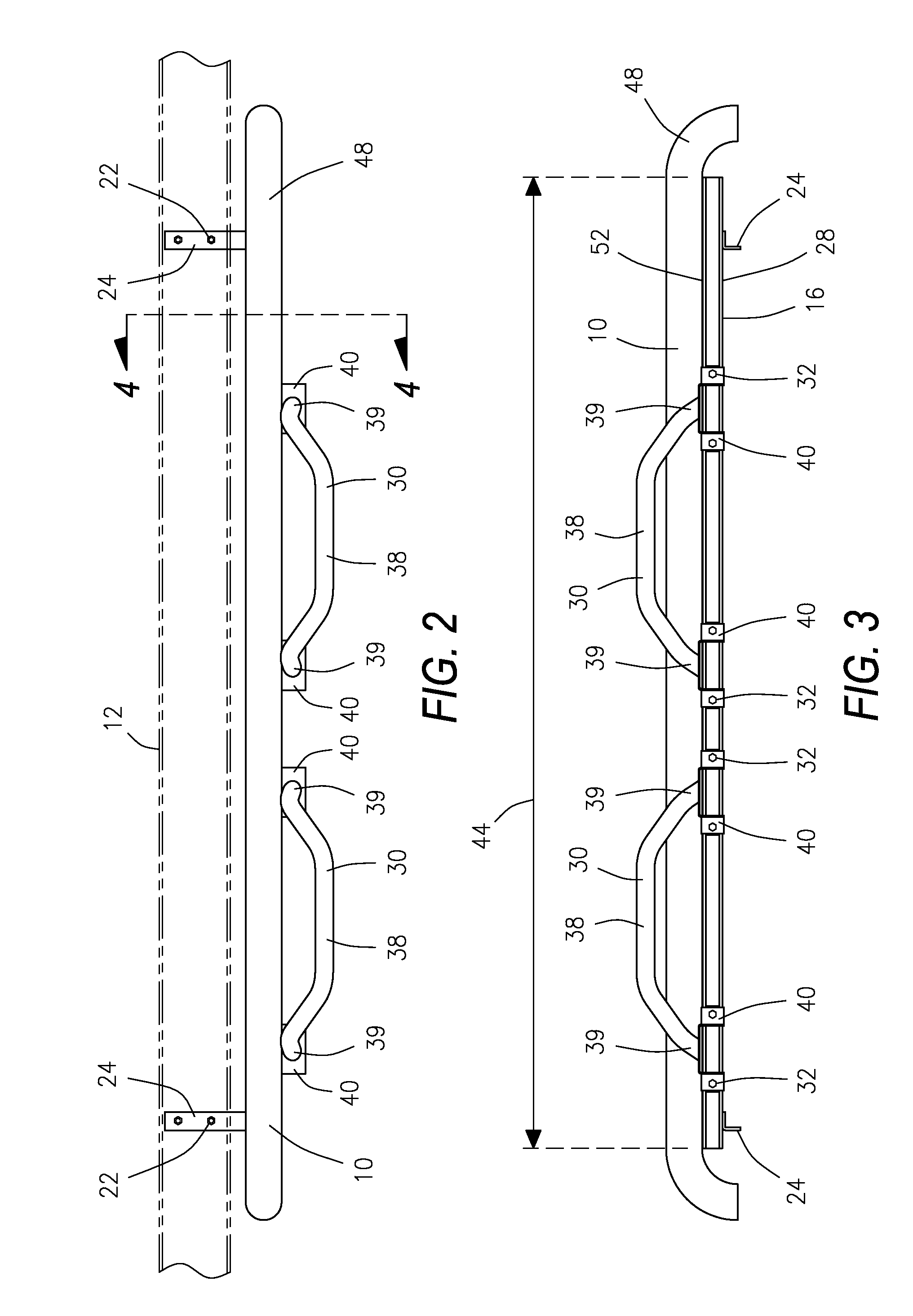
[0017]Referring now to the drawings and initially to FIG. 1, there is illustrated an adjustable vehicle step 10 that is constructed in accordance with a preferred embodiment of the present invention. The adjustable vehicle step 10 is shown in FIGS. 1 and 2 attached to a frame or body 12 of a vehicle 14 via a strong, downward facing c-channel 16 that serves as a support member for the step 10 The c-channel 16 extends longitudinally along the lower edge 18 of the side 20 of the vehicle 14. Referring also to FIGS. 3 and 4, the c-channel 16 is bolted via bolts 22 to the frame or body 12 of the vehicle 14 by metal supporting brackets 24 that are welded via weld 26 to an inwardly facing side 28 of the c-channel 16. One or more step assemblies 30 can be attached to the c-channel 16 via step bolts 32 that engage step nuts 34 that are captured within the c-channel 16 by upwardly extending lips 36 provided internally in the c-channel 16.

[0018]Referring also to FIG. 5, each step assembly 30 is...


PUM


Abstract

An adjustable vehicle step that attaches to the vehicle's frame or body via a downward facing c-channel that extends longitudinally along the lower edge of the side of the vehicle. One or more step assemblies can be attached to the c-channel so that the step assemblies extend outward and downward from under the vehicle. The step assemblies are attachable along the length of the c-channel, making the step assemblies adjustable longitudinally relative to the vehicle so that they can be positioned below the doors of the vehicle. The supporting c-channel is hidden from view by a decorative side bar that attaches to the exposed side of the c-channel making the step assemblies appear to be supported by the decorative side bar. The step assemblies used with the step can be made of various lengths and heights.

Description

CROSS-REFERENCE TO RELATED APPLICATIONS[0001]The present invention claims priority to U.S. Provisional Patent Application Ser. No. 61 / 043,222 for ADJUSTABLE VEHICLE STEP which was filed on Apr. 8, 2008.BACKGROUND OF THE INVENTION[0002]1. Field of the Invention[0003]The present invention is an adjustable vehicle step that attaches to the frame or body of the vehicle via a strong, downward facing c-channel that extends longitudinally along the lower edge of the side of the vehicle. One or more step assemblies can be attached to the c-channel and each step assembly extends outward and downward from under the vehicle. The step assemblies can be attached anywhere along the length of the c-channel, making the step assemblies adjustable longitudinally relative to the vehicle so that they can be located below the doors of the vehicle. The supporting c-channel is hidden from view by a decorative side bar that attaches to the c-channel in front of the c-channel so that the step assemblies app...

Claims


Application Information

Patent Timeline
IPC IPC(8): B60R3/00
CPCB60R3/002B60R3/02
Inventor BUNDY, TROY DON
Owner IRON CROSS AUTOMOTIVE
Why Eureka
Try Eureka