Laser aiming apparatus using a rocker

Active Publication Date: 2011-04-19
SUREFIRE LLC
View PDF34 Cites 45 Cited by
  • Summary
  • Abstract
  • Description
  • Claims
  • Application Information

AI Technical Summary

Problems solved by technology

A need exists, however, for providing a laser aiming apparatus with an improved compensation mechanism that is compact and is conveniently manipulatible by a user for effecting fine and accurate elevation and windage adjustments.

Method used


Image

  • Laser aiming apparatus using a rocker
  • Laser aiming apparatus using a rocker
  • Laser aiming apparatus using a rocker

Examples


Embodiment Construction

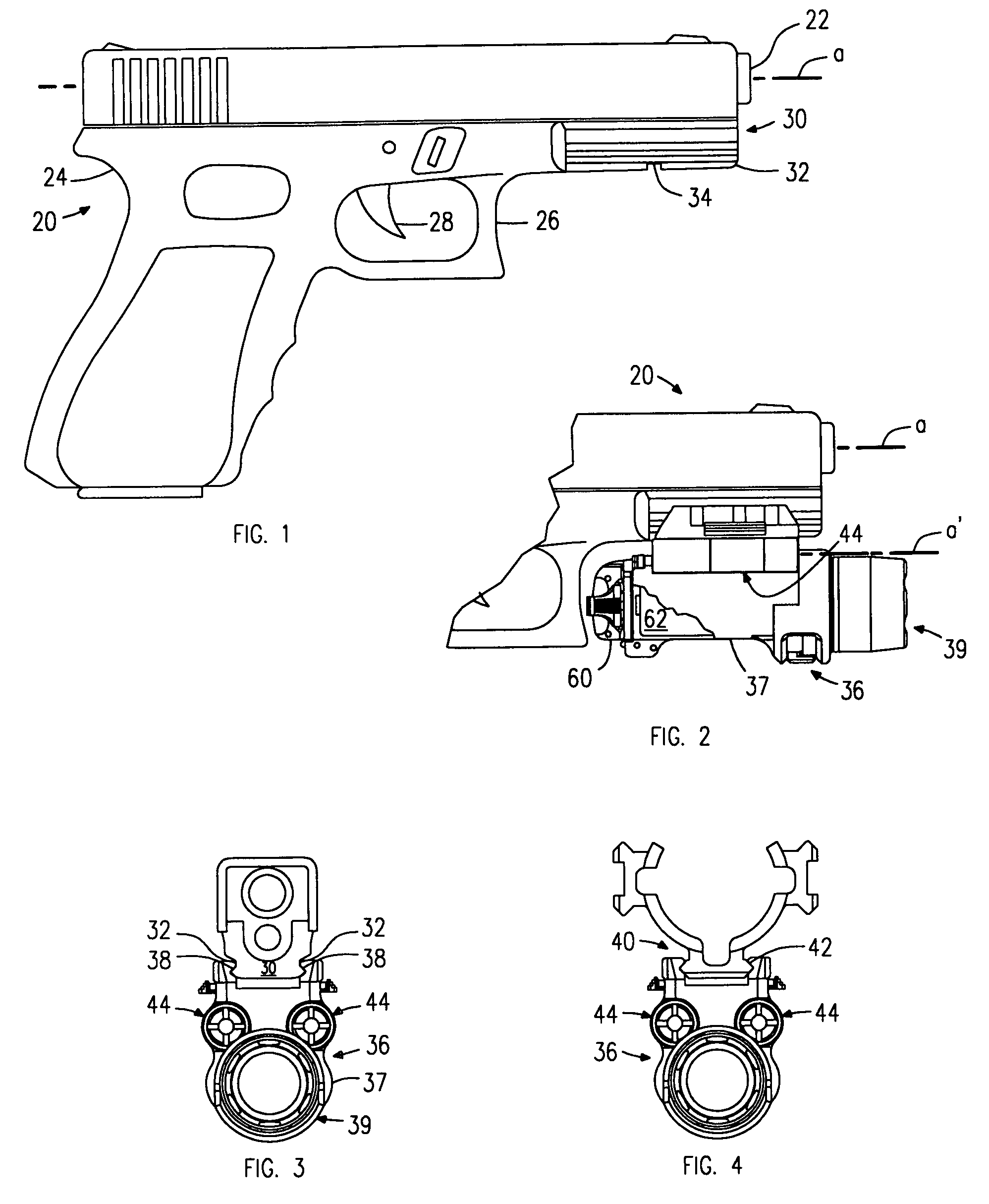
[0029]Turning to FIG. 1, there is illustrated an example of a gun or firearm 20, specifically a handgun having a barrel 22 extending along a longitudinal axis a from the handgun's frame 24 and along which a fired bullet traverses, and a trigger guard 26 in front of the handgun's trigger 28. The handgun 20 includes a longitudinal rail 30 (parallel to the longitudinal axis a) along the frame 24, below the barrel 22 and forwardly of the trigger guard 26. The rail 30 is configured with two longitudinal grooves 32, one along each side of the rail 30 and is further configured with a transverse slot 34 in the bottom surface of the rail 30. As is well known, such rails are intended for mounting an accessory such as a light for illuminating environmental and target areas, the light having a housing configured with a pair of longitudinal tongues (in this respect, see the tongues 38 for a light and laser aiming apparatus 36 as represented in FIG. 3), with such tongues 38 cooperating with the l...


PUM


Abstract

Laser aiming apparatus for accurately and conveniently applying elevation and windage adjustments to a laser beam emanating therefrom. A preferred embodiment includes a housing, which may be adapted to be mounted to a gun; a laser module in the housing and including a sleeve having a laser mounted in the sleeve for emitting a laser beam through a front end thereof along the sleeve's longitudinal axis, the sleeve being pivotally mounted in the housing about a first pivot point on the longitudinal axes of the sleeve and the housing; a rocker pivotally mounted in the housing about a second pivot point on the housing's longitudinal axis and spaced from the first pivot point, the rocker coupled to the sleeve for pivoting the sleeve about the first pivot point; and an adjustment apparatus carried by the housing and engaging the rocker for pivotally adjusting position of the rocker about the second pivot point.

Description

CROSS-REFERENCE TO RELATED APPLICATION[0001]This application claims the benefit of U.S. Provisional Patent Application No. 60 / 880,974, filed Jan. 17, 2007, incorporated in full herein by reference.BACKGROUND OF THE INVENTION[0002]This invention relates to a laser aiming apparatus, and more particularly to a laser aiming apparatus for accurately and conveniently applying elevation and windage adjustments to a laser beam emanating therefrom.[0003]One type of a laser aiming apparatus, when secured to a gun or firearm, emits a laser beam for providing an aiming mark in the form of a laser spot on a target, the spot representing the placement of a bullet to be fired by the gun at that target. To assure that the position of the laser spot on the target accurately represents the location of bullet impact, the laser aiming apparatus is typically adjusted for effecting elevation and windage compensation such that the path of the emitted laser beam coincides, at the target, with the extended ...

Claims


Application Information

Patent Timeline
Patent Type & Authority Patents(United States)
IPC IPC(8): F41G1/00
CPCF41G1/35
Inventor MATTHEWS, JOHN W.KIM, PAUL Y.WELLS, WILLIAM D.
Owner SUREFIRE LLC
Why Eureka
Try Eureka